My little team is heading down a new path in IEC fusion reactor design. I believe the concept has not been discussed much if at all on this forum and to my knowledge nothing has been built like this. The concept is to develop a near 360 degree, circumferential ion source that emits a pancake shaped sheet ion beam radially and converging at the center of a cylindrical vacuum chamber. An ion optical system has also been designed that both accelerates the ion beam to fusion relevant velocity as well as providing a focusing force in the perpendicular plane. At this point in the project we have tested an ion source design consisting two opposing 40 degree sources and run up to 25kV acceleration voltage using hydrogen. Soon we will test with deuterium and attempt to get a neutron count. Photos below. The pdf file contains much more detail about the concept and test runs.
Very nice work Rich, I'm looking forward to seeing your progress and how the device performs with deuterium. The lower the chamber pressure the more beam-gas fusion you should see. Hopefully you'll get to see that regime.
There's a paper I found some time ago that had a circumferential ion source around a geodesic grid. I don't recall the paper being particularly stellar or interesting, but it's the closest I've seen to what you've made. I'll post it later when I'm back home.
Seems like the faraday cup you are using doesn't suppress secondary electrons. This will cause the ion current to be overestimated by a factor of 3 or more.
Exciting to see such work - this really is trying* a new approach. Hope for the best and regardless of any results, do report back; and as able, updates would be highly appreciated.
Thanks for the more detailed link on your device.
Aside: I really like the direction this forum is going - threads with more advanced and cutting-edge experiments and fascinating book reviews. Really enhances the overall interest of this technical forum.
* As Richard always likes to add, if you have a good idea, then try it and see what happens.
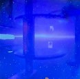
JIm, The green fluorescence (actually blue by eye) is from the glass top plate of the vacuum chamber. The plate is 5/8" thick borosilicate annealed glass from McMaster. Yeah, I know maybe not thick enough to safely support the 420 lbs or so of pressure over a 6" diameter chamber. I'm not concerned about breakage for personnel just concerned about glass fragments finding their way into the turbo pump.
William, True that there is (could be) a secondary emission issue since my home made Faraday cup does not have a suppression grid. Literature mentions numbers as high as 2or 3X for H2 at 10keV on metal. However these data points are usually done under high vacuum conditions not at the 1mTorr pressure as in my case. So the secondary issue is complex as there are competing processes going on such as (-e,+H2) recombination as well as beam neutrals. In my case I'm more interested in just getting the ion sources to work properly and understanding the issues related to the ion focusing and discharge quenching when the extraction field is too high (I may need a suppressor grid on the ion source when the negative accelerating potential get to high and quenches the ionization). The simple answer to the secondary issue is to include a suppression grid inside the cup and do some modeling to assure no secondaries are escaping the cup. Secondaries would have low energy of a few tens of eV or less so it won't take much of a potential difference inside to block those from escaping. I'll look into that.
Rick
Thanks for responding to my question. I was asking about the bluish, ghosty looking stuff off the glass. I was asking about the small green dot. I suppose what I'm seeing is a reflection of some green light in your lab.
Attachments
Screenshot_20230412-115928_Chrome.jpg (43.39 KiB) Viewed 6517 times
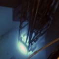
LoL, sorry my mistake. That's green P1 phosphor (540nm) lighting up a screw head inside the chamber. A while ago I tried using a phosphor screen to get a visual look at the ion beam profile. It was a home made little screen coated on ITO glass. Well, I got to see the beam for a minute but it didn't last more than a few more minutes under the ion bombardment. Phosphor was blasted off the screen and ended up all over the inside of the chamber. It lit up like a Christmas tree. I guess there's still some residual P1 left in the chamber.