- The device must be portable.
- must be safe to operate, even by spectators.
- It must be reliable enough to be operated almost continuously for 12 hours.
- The system must be straightforward so it can be easily explained to a layperson.
The chamber is cylindrical with 100mm diameter and about 100mm depth. There are 5 DN25 KF flanges and one DN40. To the DN25 there are connected: pumping line cut-off valve, HV feedthrough, micrometric needle valve for pressure control, and TC vacuum transducer. On the DN40 there is a small viewport which may be used for the camera or for the optical spectrometer.
Because of those problems I’ve picked up another supply - this time an real oldtimer: 1971 Vacuum tube ZWN-2,5 rated 2.5kV and about 20mA. After brief overhaul it turned out to be built like a tank and fully functional, including capacitors.
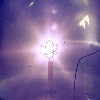
The second supply is reliable, and much nicer to operate. The voltage can be adjusted with 200V increments plus additional knobs for 20 and 2V steps. This time a stable and controllable plasmoid was formed.
For the moment I think that the inner grid is a bit too big for the chamber size and that maybe installation of the spherical outer grid may improve focusing. But generally I think this setup should give some fun to the visitors (they will be allowed to adjust the voltage and pressure themselves).