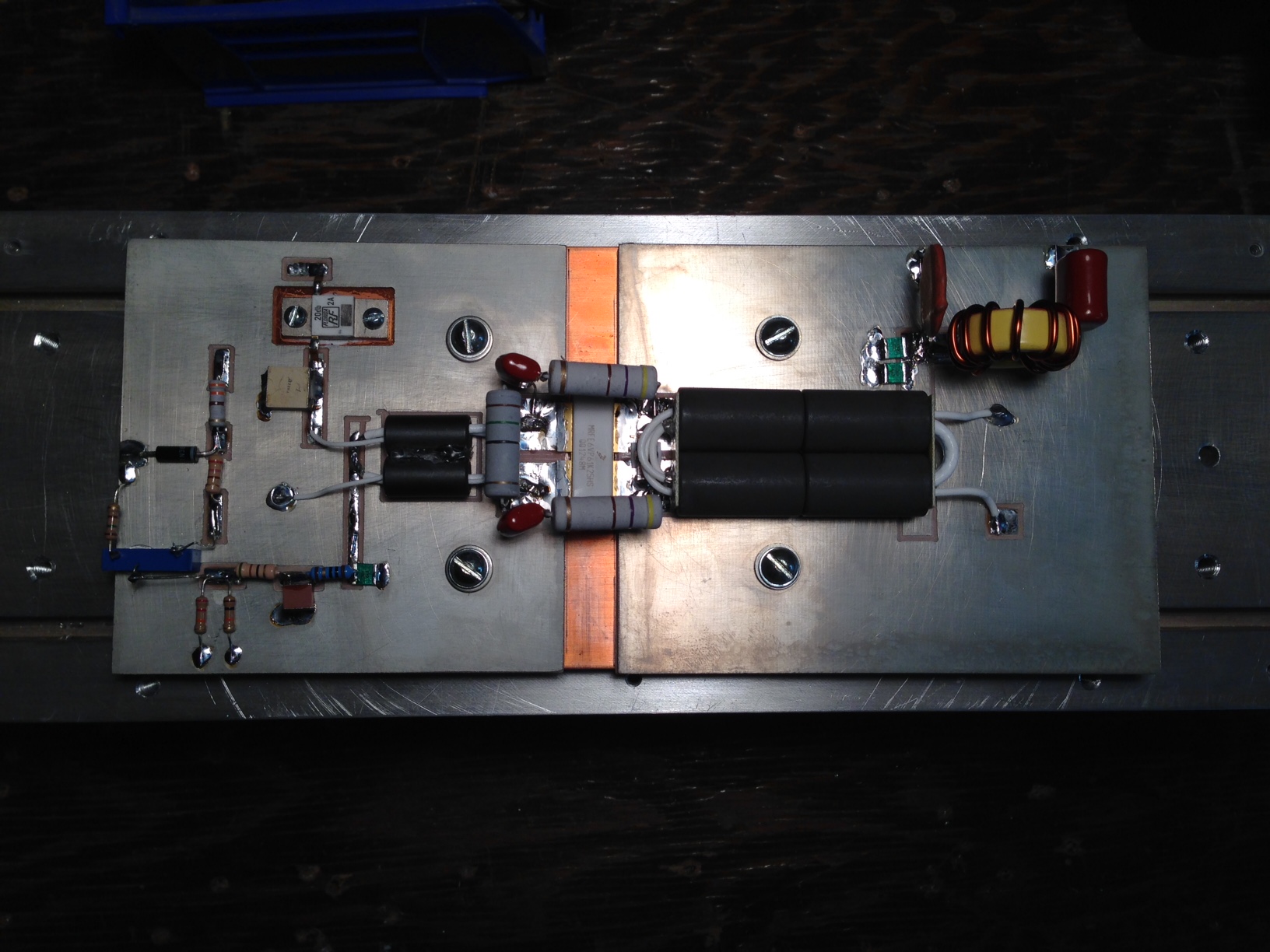
Homemade RF Amplifier
http://www.qsl.net/kf8od/ldmos.html
Purchasable RF Amplifier

https://eb104.ru/internet-magazin-shiro ... for-blf578
Werenr Engel RF Supply
viewtopic.php?f=12&t=11456


8.71:1 indicates the maximum VSWR the amplifier can see with a 1db attenuator on the output. Here is more info on itMake a 1dB attenuator to put on the output - you lose 20% of your output at the gain of not blowing the devices
This immediately means the VSWR can not go over 8.7:1 with a dead short or open on the output (the two worst possible cases)