Plasma Backdraft Arrester
This high voltage gas feed problem has been driving me nuts, and today I came up with a simple idea which might work.
Basically its like a wine makers glass air lock with a bit of diff pump oil in it. Have any of you guys seen something like this being used before and do you think of the idea, will it work?
Steven
Low Tech Gas Feed Solution
-
Steven Sesselmann
- Posts: 2128
- Joined: Wed Aug 10, 2005 9:50 pm
- Real name: Steven Sesselmann
- Location: Sydney - Australia
- Contact:
Low Tech Gas Feed Solution
- Attachments
-
- Gas Bubbler
http://www.gammaspectacular.com - Gamma Spectrometry Systems
https://www.researchgate.net/profile/Steven_Sesselmann - Various papers and patents on RG
https://www.researchgate.net/profile/Steven_Sesselmann - Various papers and patents on RG
-
Rich Feldman

- Posts: 1471
- Joined: Mon Dec 21, 2009 6:59 pm
- Real name: Rich Feldman
- Location: Santa Clara County, CA, USA
Re: Low Tech Gas Feed Solution
Nice picture and nice idea, Steven.
Let's be sure we have the same understanding of "Plasma Backdraft Arrester".
Left side tube connects to apparatus (ion gun?) at high voltage and very low pressure.
You don't want an electric discharge inside the hose, back to a gas flow control at ground potential.
HV isolation comes from the oil column in U-tube, right?
Gas pressure on the source side of U-tube will be on the order of a couple of torr, to support the oil level mismatch. Gas bubbles will expand as they rise through the gradient of hydrostatic pressure.
Don't know how much much they will expand, since surface tension will also be important. How soon will you have a picture for us?
Sparse bubbles probably won't reduce the dielectric breakdown voltage much. Were you ever told that it's dangerous to pee off the side of a bridge, if there are electric train wires not far below?
All models are wrong; some models are useful. -- George Box
-
Steven Sesselmann
- Posts: 2128
- Joined: Wed Aug 10, 2005 9:50 pm
- Real name: Steven Sesselmann
- Location: Sydney - Australia
- Contact:
Re: Low Tech Gas Feed Solution
Yes, yes and yes, that's the basic idea..Rich Feldman wrote: Let's be sure we have the same understanding of "Plasma Backdraft Arrester".
Left side tube connects to apparatus (ion gun?) at high voltage and very low pressure.
You don't want an electric discharge inside the hose, back to a gas flow control at ground potential.
HV isolation comes from the oil column in U-tube, right?
Well all of this will depend on the viscosity of the diff pump oil, but from what I have seen before the synthetic oils have a low viscosity.Gas pressure on the source side of U-tube will be on the order of a couple of torr, to support the oil level mismatch. Gas bubbles will expand as they rise through the gradient of hydrostatic pressure.
Don't know how much much they will expand, since surface tension will also be important.
First I have to mentally prepare myself to dump the electronic gas flow project I spent the last 3 months on, then move on swiftly and find some Swagelok to glass fittings. I have a local glass blower just up the road who can make it for me.How soon will you have a picture for us?
If I ever feel the urge while crossing a railway bridge I shall remember not to do any target practiceSparse bubbles probably won't reduce the dielectric breakdown voltage much. Were you ever told that it's dangerous to pee off the side of a bridge, if there are electric train wires not far below?
http://www.gammaspectacular.com - Gamma Spectrometry Systems
https://www.researchgate.net/profile/Steven_Sesselmann - Various papers and patents on RG
https://www.researchgate.net/profile/Steven_Sesselmann - Various papers and patents on RG
-
Roberto Ferrari
- Posts: 364
- Joined: Tue Mar 02, 2004 12:21 pm
- Real name: Roberto Ferrari
- Location: Argentina
- Contact:
Re: Low Tech Gas Feed Solution
Hi
I don’t understand the issue.
With a peek tubing you can feed deuterium to your chamber.
1/16” to NPT Swagelok adaptor would solve the joining point.
Do I miss something?
I don’t understand the issue.
With a peek tubing you can feed deuterium to your chamber.
1/16” to NPT Swagelok adaptor would solve the joining point.
Do I miss something?
-
John Futter
- Posts: 1850
- Joined: Wed Apr 21, 2004 10:29 pm
- Real name: John Futter
- Contact:
Re: Low Tech Gas Feed Solution
Roberto
I have lit up a 30m roll of polyurethane tubing like a giant neon bulb. Pashens law gives us a clue as to why this happens.
I think
Steven is trying to find a way to prevent his terminal voltage being shorted out via this discharge.
however his bubbles will grow in size by 1000's of times as the perceived pressure goes lower in the insulating liquid
-
Steven Sesselmann
- Posts: 2128
- Joined: Wed Aug 10, 2005 9:50 pm
- Real name: Steven Sesselmann
- Location: Sydney - Australia
- Contact:
Re: Low Tech Gas Feed Solution
John,
Why do you think the bubbles will get that big?
Pressure on the gas side is about the same as on the chamber side, so the gas can't expand all that much. I would still be using the Mass Flow Controller (MKS 649) to control the pressure in the chamber, but this time it will be at ground potential which makes everything so much simpler. The size of the bubbles would be function of the surface tension in the liquid, which I suppose can only really be confirmed by a test.
Steven
http://www.gammaspectacular.com - Gamma Spectrometry Systems
https://www.researchgate.net/profile/Steven_Sesselmann - Various papers and patents on RG
https://www.researchgate.net/profile/Steven_Sesselmann - Various papers and patents on RG
-
Roberto Ferrari
- Posts: 364
- Joined: Tue Mar 02, 2004 12:21 pm
- Real name: Roberto Ferrari
- Location: Argentina
- Contact:
Re: Low Tech Gas Feed Solution
Got it!
Cannot put a grounded metal sieve or mesh in order to drain current to ground while deuterium still goes through?
Cannot put a grounded metal sieve or mesh in order to drain current to ground while deuterium still goes through?
-
Rich Feldman
- Posts: 1471
- Joined: Mon Dec 21, 2009 6:59 pm
- Real name: Rich Feldman
- Location: Santa Clara County, CA, USA
Re: Low Tech Gas Feed Solution
Roberto, Steven is not talking about feeding gas to fusors.
In a fusor, metal fitting at vacuum end of gas line can be grounded. That's not always the case when the gas is for ion guns, particle accelerators, etc.
Steven, I bet John was thinking of the change in hydrostatic pressure from a couple of torr at bottom of oil to low micron level at top. Equilibrium volume of bubbles would change by the inverse factor, except for the extra internal pressure to balance surface tension.
I bet formulas and numbers applicable to our case can be found this paper, with theory and pictures of expanding gas bubbles in microgravity. https://ntrs.nasa.gov/archive/nasa/casi ... 019007.pdf
[edit] Consider a gas bubble of radius 1 mm in water. Surface tension at 20°C is about .073 N/m.
The equilibrium pressure inside the bubble exceeds the outside pressure by 2T/r = 146 Pa. About 1 torr according to this unreviewed analysis.
[edit some more] For a small gas flow, it might help if U-tube were modified to make the bubbles consistently tiny and frequent. This picture shows about 1 sccm of air bubbling through water at about 1 atmosphere.
as presented here: viewtopic.php?f=6&t=8725&p=60017 Next round should have vacuum on the discharge side.
In a fusor, metal fitting at vacuum end of gas line can be grounded. That's not always the case when the gas is for ion guns, particle accelerators, etc.
Steven, I bet John was thinking of the change in hydrostatic pressure from a couple of torr at bottom of oil to low micron level at top. Equilibrium volume of bubbles would change by the inverse factor, except for the extra internal pressure to balance surface tension.
I bet formulas and numbers applicable to our case can be found this paper, with theory and pictures of expanding gas bubbles in microgravity. https://ntrs.nasa.gov/archive/nasa/casi ... 019007.pdf
[edit] Consider a gas bubble of radius 1 mm in water. Surface tension at 20°C is about .073 N/m.
The equilibrium pressure inside the bubble exceeds the outside pressure by 2T/r = 146 Pa. About 1 torr according to this unreviewed analysis.
[edit some more] For a small gas flow, it might help if U-tube were modified to make the bubbles consistently tiny and frequent. This picture shows about 1 sccm of air bubbling through water at about 1 atmosphere.
Last edited by Rich Feldman on Tue Jan 17, 2017 7:28 pm, edited 1 time in total.
All models are wrong; some models are useful. -- George Box
-
Roberto Ferrari
- Posts: 364
- Joined: Tue Mar 02, 2004 12:21 pm
- Real name: Roberto Ferrari
- Location: Argentina
- Contact:
Re: Low Tech Gas Feed Solution
Thanks Rich!
-
Steven Sesselmann
- Posts: 2128
- Joined: Wed Aug 10, 2005 9:50 pm
- Real name: Steven Sesselmann
- Location: Sydney - Australia
- Contact:
Re: Low Tech Gas Feed Solution
http://www.gammaspectacular.com - Gamma Spectrometry Systems
https://www.researchgate.net/profile/Steven_Sesselmann - Various papers and patents on RG
https://www.researchgate.net/profile/Steven_Sesselmann - Various papers and patents on RG
-
prestonbarrows
- Posts: 211
- Joined: Sun Jun 24, 2012 1:27 am
- Real name:
Re: Low Tech Gas Feed Solution
I would imagine a 'U-trap' like this would lead to unstable operation where a volume builds up on the high pressure side then 'burps' over to the low pressure side sporadically. The magnitude of such surges may be acceptable, but they will always fundamentally be present.
The best approach to have a controlled flow of gas at high voltage is to locate a mass flow controller at the floating potential. You can still keep your feed bottle at ground in most cases. As the feedline across the potential drop will be at ~15 PSI, you can bridge that up to hundreds of kV without Paschen biting your ass or needing to jump though any ridiculous hoops for tubing path length.
Just keep above 1 Torr-cm and you should be OK.
If you absolutely can't deal with that, you can always float a lecture bottle at operating voltage. This gives zero potential drop across any gas lines but requires some thought about where the bottle and regulator will live.
The main rub for all of this is getting an analog signal and DC power to the floating MFC. For hobbiest situations, you can get away with a floating supply such as a battery or supercap for significant periods of time. Beyond that, you need to resort to motor generators and fiber optic communications.
-
Steven Sesselmann
- Posts: 2128
- Joined: Wed Aug 10, 2005 9:50 pm
- Real name: Steven Sesselmann
- Location: Sydney - Australia
- Contact:
Re: Low Tech Gas Feed Solution
Preston,
Thanks for advise, everything you say makes perfect sense, the only problem is I have been there and done that. (see my thread here) viewtopic.php?f=6&t=10479
Tried floating the MFC, tried powering it with batteries, tried optical connections, etc.etc. nothing stays up when the reactor starts fusing, huge voltage spikes mess with the electronics, which is why I am heading down the road with my "flux capacitor" invention.
I tend to agree with you that the gas on the low pressure side will have to build up quite a bit before burping a bubble, so I will be making it a little bit differently with a tiny hole at the bottom of the oil side.
I also have another idea I want to try, which is simply to put a bit of dry sand in the U trap, this will allow the gas to flow through, but prevent electrons ionising the gas through the sand, because the mean free path would be too short. This solution will be less messy and possibly work better. This is all R&D and I am at the point where I will try any simple idea.
Steven
http://www.gammaspectacular.com - Gamma Spectrometry Systems
https://www.researchgate.net/profile/Steven_Sesselmann - Various papers and patents on RG
https://www.researchgate.net/profile/Steven_Sesselmann - Various papers and patents on RG
-
Richard Hull

- Moderator
- Posts: 15027
- Joined: Fri Jun 15, 2001 9:44 am
- Real name: Richard Hull
Re: Low Tech Gas Feed Solution
It is to be remembered that the fusor, the FICS and any other device that supports what is, in effect, a Townsend arc breakdown in a partial vacuum will be a great noise source across a rather broad spectrum, whether the device is doing fusion of not. Many great custom noise generators are constructed with this type of device at there core. Yes Virginia they do make expensive noise generators for sale in the world of electronics and RF engineering.
It is the devil's own work trying to float or remote sense, sensitive instrumentation in a noisy environment.
Richard Hull
It is the devil's own work trying to float or remote sense, sensitive instrumentation in a noisy environment.
Richard Hull
Progress may have been a good thing once, but it just went on too long. - Yogi Berra
Fusion is the energy of the future....and it always will be
The more complex the idea put forward by the poor amateur, the more likely it will never see embodiment
Fusion is the energy of the future....and it always will be
The more complex the idea put forward by the poor amateur, the more likely it will never see embodiment
-
Dennis P Brown

- Posts: 3189
- Joined: Sun May 20, 2012 10:46 am
- Real name: Dennis Brown
Re: Low Tech Gas Feed Solution
Richard, when you point out
All I can say is, and this is from recent experience, I've learned this to be an understatement compared to the reality! Also, when the star ground configuration is used (and always a good idea to use this for safety!), one is also "piping in" huge voltage surges into the ground system which all your electronics can easily "see". My poor counter ran at the 120 Hz from the fusor!
I am slowly gathering together and assembling the equipment to have a battery supplied 2 kV DC and 120 AC power supply (for my counter) to operate/read my fully shielded Russian neutron counter. I will use a shielded cable/detector and locate the HV & counter some distance away (alas, shielding the car battery and HV x-former & variac is not practical as of yet.)
I do not think this subject in the detector FAQ's section is sufficiently emphasized as it so richly deserves.
My fusor - which easily achieves fusion conditions and (finally!) is highly stable - is, currently, as you correctly point out is just a very complex noise machine. Further, at least this aspect of a real fusor is its easiest property to demonstrate - LOL!
,Townsend arc breakdown in a partial vacuum will be a great noise source across a rather broad spectrum
All I can say is, and this is from recent experience, I've learned this to be an understatement compared to the reality! Also, when the star ground configuration is used (and always a good idea to use this for safety!), one is also "piping in" huge voltage surges into the ground system which all your electronics can easily "see". My poor counter ran at the 120 Hz from the fusor!
I am slowly gathering together and assembling the equipment to have a battery supplied 2 kV DC and 120 AC power supply (for my counter) to operate/read my fully shielded Russian neutron counter. I will use a shielded cable/detector and locate the HV & counter some distance away (alas, shielding the car battery and HV x-former & variac is not practical as of yet.)
I do not think this subject in the detector FAQ's section is sufficiently emphasized as it so richly deserves.
My fusor - which easily achieves fusion conditions and (finally!) is highly stable - is, currently, as you correctly point out is just a very complex noise machine. Further, at least this aspect of a real fusor is its easiest property to demonstrate - LOL!
-
Richard Hull
- Moderator
- Posts: 15027
- Joined: Fri Jun 15, 2001 9:44 am
- Real name: Richard Hull
Re: Low Tech Gas Feed Solution
In general well shileded cables running to properly shielded instruments is more than adequate to reduce noise to a windowable level. If using NIM gear you need to remember to terminate the line with the characteristic impedance...For most NIM this is 94 ohms, however, common 75 ohm terminators seem to do OK. Still, a 94 ohm terminator is easy enough to fabricate using a BNC male connector.
Richard Hull
Richard Hull
Progress may have been a good thing once, but it just went on too long. - Yogi Berra
Fusion is the energy of the future....and it always will be
The more complex the idea put forward by the poor amateur, the more likely it will never see embodiment
Fusion is the energy of the future....and it always will be
The more complex the idea put forward by the poor amateur, the more likely it will never see embodiment
-
Steven Sesselmann
- Posts: 2128
- Joined: Wed Aug 10, 2005 9:50 pm
- Real name: Steven Sesselmann
- Location: Sydney - Australia
- Contact:
Re: Low Tech Gas Feed Solution
Looks like I finally invent something that works 
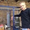
The plasma backdraft arrestor (Flux Capacitor) actually works. My local glass blower Ken (Custom Blown Glass in Sydney) made up the airlock from borosilicate glass. What is not seen on the sketch is that the U shaped connector comes to a fine point with a tiny hole on the high vacuum side, which makes tiny bubbles as the gas is vented in.
I found an eBay supplier in india selling small bottles of silicone oil for Diff pumps for $6.00 ( http://www.ebay.com/itm/272518309957 ) can't complain about that price, and it arrived fast.
Here is a pretty picture before adding the oil.
The connections are 1/4" Swagelok hose barbs mating with 6 mm glass barbs, and the hose is special high vacuum hose.
After adding the oil, the plasma stopped and I can bring the chamber down to sub micron pressure yet I can still vent in the gas which bubbles up nicely. The only thing I might have to improve is the HV stand off on the outside of the Flux Capacitor, I should have made it longer, possibly with a few coils.
I can now mount the mass flow controller and deuterium cylinder at ground potential and hook it up to the DAQ in the same way as the other equipment, thereby eliminating the nightmare of trying to float the gas supply. Thanks to Doc Brown for the inspiration on this one...
Steven
The plasma backdraft arrestor (Flux Capacitor) actually works. My local glass blower Ken (Custom Blown Glass in Sydney) made up the airlock from borosilicate glass. What is not seen on the sketch is that the U shaped connector comes to a fine point with a tiny hole on the high vacuum side, which makes tiny bubbles as the gas is vented in.
- Sketch
Here is a pretty picture before adding the oil.
- Flux Capacitor
After adding the oil, the plasma stopped and I can bring the chamber down to sub micron pressure yet I can still vent in the gas which bubbles up nicely. The only thing I might have to improve is the HV stand off on the outside of the Flux Capacitor, I should have made it longer, possibly with a few coils.
I can now mount the mass flow controller and deuterium cylinder at ground potential and hook it up to the DAQ in the same way as the other equipment, thereby eliminating the nightmare of trying to float the gas supply. Thanks to Doc Brown for the inspiration on this one...
Steven
http://www.gammaspectacular.com - Gamma Spectrometry Systems
https://www.researchgate.net/profile/Steven_Sesselmann - Various papers and patents on RG
https://www.researchgate.net/profile/Steven_Sesselmann - Various papers and patents on RG