In light of Richard Hull's recent FAQ regarding the neutron club, I'm making a status update & progress report.
I've only registered on this forum recently, so I'm hoping this will serve as a extended introduction.
The chamber was built by Wieder Labs, it's a 6" diameter sphere, sealed with 8" CF flanges. It has 2 2.75" and 4 1.33" CF flanges for accessories. Beautiful inside and out.
Right now it only has a Hastings DV-6 tube on it.
There's a Welch 1400 on the bottom tray of the cart. It's a pristine pump, even the paint still looks nice. Considering they're nearly $2000 new, I practically stole it for $310 shipped.
The rackmount chassis is a 12U. It currently has:
1U switch panel
3U Hastings custom-built vacuum gauge panel (a great eBay find, it was less than $50). A coworker just bought a Hastings reference tube for his meters, and I was able to calibrate mine with it as well.
4U Variac panel, built by me with yet another eBay gem, a new-in-box General Radio W5 Variac. It will be used to fine-tune the diffusion pump heater.
2U Glassman -20kV 30mA power supply (I realize this is on the ragged edge of necessary voltage)
The second photo is a Varian 0936 diffusion pump. It looks really good, but had a bad heater. FYI, Tempco makes an exact replacement band heater, p/n NHL00186. My coworker and I are making an adapter tube, 2.75" CF on one end and a custom 3.5" OD 3-screw-hole flange on the other.
3rd photo is a closer look at the chamber.
4th photo shows the adapter tube parts sitting on top of the diffusion pump, no welding/machining done yet. You can also see a 100cc bottle of Octoil in that photo.
Last photo is the tentative design. It doesn't account for any deuterium or neutron systems yet.
I have a Varian right angle valve on the way. There's a conflat elbow sitting on the cart next to the chamber, and not pictured are various bolts, hoses, fittings, ceramic alumina tubes & SS wire for the grid, and a few cables.
I've also ordered an HV feedthrough and viewport.
I expect to be making vacuum test runs in 2 to 3 weeks.
Edit: I made a mistake, I said the PS was a Spellman, it's actually a Glassman.
Archived - Fusor progress, info & photos
-
Daniel Firth
- Posts: 36
- Joined: Wed Apr 04, 2012 10:31 pm
- Real name:
Archived - Fusor progress, info & photos
- Attachments
-
-
-
-
-
-
Jim Kovalchick
- Posts: 717
- Joined: Wed Apr 13, 2011 8:00 pm
- Real name:
Re: Fusor progress, info & photos
I like your emphasis on safety as shown by the neat and organized appearance and the handy extinguisher.
You will be able to do nice demo work with that power supply, but I wouldn't waste deuterium on it until you can do at least -25 to 30 kV unless all you are going for is star mode pictures.
Have you thought about a camera or mirror for viewing without x-rays?
good luck.
Jim Kovalchick
You will be able to do nice demo work with that power supply, but I wouldn't waste deuterium on it until you can do at least -25 to 30 kV unless all you are going for is star mode pictures.
Have you thought about a camera or mirror for viewing without x-rays?
good luck.
Jim Kovalchick
-
Conrad Farnsworth
- Posts: 135
- Joined: Wed Jul 07, 2010 9:35 pm
- Real name: Conrad Farnsworth
Re: Fusor progress, info & photos
Daniel,
I really like your setup! Deuterium could easily be metered in through a double sided flange in between the valve and the chamber itself. The setup you have is looking very professional!
-Conrad
I really like your setup! Deuterium could easily be metered in through a double sided flange in between the valve and the chamber itself. The setup you have is looking very professional!
-Conrad
-
Richard Hull

- Moderator
- Posts: 15023
- Joined: Fri Jun 15, 2001 9:44 am
- Real name: Richard Hull
Re: Fusor progress, info & photos
This is really a fine piece of work Daniel. You have given us a lot of data in the background of your system. You are well on your way, I see. I have achived this.
Richard Hull
Richard Hull
Progress may have been a good thing once, but it just went on too long. - Yogi Berra
Fusion is the energy of the future....and it always will be
The more complex the idea put forward by the poor amateur, the more likely it will never see embodiment
Fusion is the energy of the future....and it always will be
The more complex the idea put forward by the poor amateur, the more likely it will never see embodiment
-
Andrew Seltzman
- Posts: 810
- Joined: Sun Feb 01, 2004 8:02 pm
- Real name: Andrew Seltzman
- Contact:
Re: Archived - Fusor progress, info & photos
Daniel,
You said you got your vacuum chamber form wieder labs, (http://www.wiederlabs.com/) and I remember that some of us had questions on the quality of their work. Do you have any pictures of their welds / or what the chamber looks like inside?
Andrew
You said you got your vacuum chamber form wieder labs, (http://www.wiederlabs.com/) and I remember that some of us had questions on the quality of their work. Do you have any pictures of their welds / or what the chamber looks like inside?
Andrew
Andrew Seltzman
www.rtftechnologies.org
www.rtftechnologies.org
-
Daniel Firth
- Posts: 36
- Joined: Wed Apr 04, 2012 10:31 pm
- Real name:
Re: Archived - Fusor progress, info & photos
When it was being built, I asked for photos of the construction and got a bunch.
Here are some photos of the welds during different stages of the build.
I don't remember the numbers now, but at one point I added up the cost of the components (4 1.33 flanges, 2 2.75 flanges, 2 8" flanges) from Kurt Lesker, and I think it was roughly 2/3 of how much it cost to just have Wieder Labs do the whole thing.
- Attachments
-
-
-
-
-
Tyler Christensen
- Site Admin
- Posts: 551
- Joined: Mon Feb 23, 2009 9:08 pm
- Real name:
Re: Archived - Fusor progress, info & photos
Wow, that is very unacceptable welding quality for a professionally made vacuum chamber. I'll be sure to stay away from that company.
-
Andrew Seltzman
- Posts: 810
- Joined: Sun Feb 01, 2004 8:02 pm
- Real name: Andrew Seltzman
- Contact:
Re: Archived - Fusor progress, info & photos
Agreed, they used way too much weld current, you can see the melt through to the outside. You did a nice job of cleaning it up though.
Is it confirmed to be leak proof?
Andrew
Is it confirmed to be leak proof?
Andrew
Andrew Seltzman
www.rtftechnologies.org
www.rtftechnologies.org
-
Daniel Firth
- Posts: 36
- Joined: Wed Apr 04, 2012 10:31 pm
- Real name:
Re: Archived - Fusor progress, info & photos
I didn't do anything to clean it up. Those are images are in-progress before it was shipped to me.
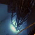
Here's how it looks inside as-delivered. I'm experimenting with different grid techniques here.
Here's how it looks inside as-delivered. I'm experimenting with different grid techniques here.
- Attachments
-
-
-
Tyler Christensen
- Site Admin
- Posts: 551
- Joined: Mon Feb 23, 2009 9:08 pm
- Real name:
Re: Archived - Fusor progress, info & photos
In all honesty, if there is a return policy I would send that chamber back. If it's not leaky, it's bound to be full of virtual leaks that you will discover down the line as you perfect your system. The welds are so bad I can see multiple places visually where gross virtual leaks could occur.
-
RobertTubbs
- Posts: 209
- Joined: Thu Mar 05, 2009 1:49 pm
- Real name:
Re: Archived - Fusor progress, info & photos
Someone once before asked if this company was a good one to buy from. The response was quite clear that this is not a reputable or even competent company to buy from. Omitting the various stolen pictures lining his website (which by the way changes almost monthly) of other peoples fusors the quality of the weld looks like someone took a Harbour Freight flux core MIG welder to it and then ground the bead down until it looked a little less embarrassing.
Granted, I'm sure you'll make neutrons with it if you can squirt enough JB-Weld into all the cracks, but it won't be anything compared to a $300 e-beam/tig welded second hand chamber off eBay that might have been a little less aesthetically pleasing. Anticipate virtual leaks for all eternity - they're well earned.
I'd ask for my money back,
RT
-
swiederhold
- Posts: 8
- Joined: Mon May 07, 2012 12:24 am
- Real name:
- Contact:
Re: Archived - Fusor progress, info & photos
I am the owner and operator of Wieder Labs.
Obviously you are free to critique my work. However, can you please specify which image on my web site you are claiming is "stolen"?
Obviously you are free to critique my work. However, can you please specify which image on my web site you are claiming is "stolen"?
-
RobertTubbs
- Posts: 209
- Joined: Thu Mar 05, 2009 1:49 pm
- Real name:
Re: Archived - Fusor progress, info & photos
Oh my, my mistake it appears you've since changed the photos you use to advertise your product to something other than Brian Mcdermott and Richard Hull's intellectual property. While I don't recognise this "batch," that doesn't mean you haven't stolen these aswell. Carry on then you vulture.
RT
RT
-
swiederhold
- Posts: 8
- Joined: Mon May 07, 2012 12:24 am
- Real name:
- Contact:
Re: Archived - Fusor progress, info & photos
I have NEVER used pictures of other people's fusors. The fusor pictures on my site, now or previously, are of MY personal fusor. Get your facts straight before you defame people.
-
John Taylor

- Posts: 97
- Joined: Wed Jun 22, 2011 1:43 pm
- Real name:
- Location: Dardanelle, Arkansas
Re: Archived - Fusor progress, info & photos
I purchased a 6" spherical chamber from the same source and although the welds may not look as pretty as some would prefer, I have had no problems achieving an acceptable vacuum for the experiment I purchased it for, although in the E-4 torr only and without appreciable heat. It was supplied to me as a custom chamber with (8) equidistant 1.33 CF flanges and (2) 2.75 CF flanges ("TOP" and "BOTTOM"). The 2.75" flanges are sealed with copper and have not given me any apparent problems with leaks that I am aware of. The 8" flange joining the two hemispheres is sealed with copper as well. The 1.33" flanges are sealed with Viton-A O-rings. Prior to baking the chamber, I had some probable virtual leaks that have diminished quite a bit with baking under vacuum. I am not producing plasma or much heat in this chamber (not a fusor) but am happy that I bought this for less than $700.00. My chamber was bead-blasted inside and out.
*The first pic shows the chamber as shipped to me.
*Second pic shows outside of chamber while assembling to a manifold.
*Third pic shows inside of chamber bottom hemisphere.
If I ever convert it into a fusor and try to pull a deeper vacuum, it may be a different story, but this chamber seems adequate as far as weld quality is concerned.
John Taylor
- Attachments
-
-
-
-
Richard Hull
- Moderator
- Posts: 15023
- Joined: Fri Jun 15, 2001 9:44 am
- Real name: Richard Hull
Re: Archived - Fusor progress, info & photos
The proof is in the pudding gentlemen. Before trashing, "let the experiment be done", (Ben Franklin). Yes, it looks as if too much heat was used, but the welds seem to have cleaned up well and I would await real runs to tell the tale.
Virtual leaks are as universal as the sea sickness. They are to be expected, but only a real pump down and the report taken off a good gauge is needed.
Richard Hull
Virtual leaks are as universal as the sea sickness. They are to be expected, but only a real pump down and the report taken off a good gauge is needed.
Richard Hull
Progress may have been a good thing once, but it just went on too long. - Yogi Berra
Fusion is the energy of the future....and it always will be
The more complex the idea put forward by the poor amateur, the more likely it will never see embodiment
Fusion is the energy of the future....and it always will be
The more complex the idea put forward by the poor amateur, the more likely it will never see embodiment
-
David Geer
- Posts: 136
- Joined: Wed Nov 24, 2010 7:51 am
- Real name:
- Location: Colorado Springs, CO
Re: Archived - Fusor progress, info & photos
I'm also a welder and I'd have you go back to school before anyone would even remotely be able to purchase the items. The lines are horrible, too much heat, too much beading. These are amateurish mistakes from an apprentice and not a journeyman, craftsman or mastercraftsman's work.
You may run the risk of a blow-out/implosion from the poorly welded areas that may create dangerous shrapnel. Just an FYI.
You may run the risk of a blow-out/implosion from the poorly welded areas that may create dangerous shrapnel. Just an FYI.
- David Geer
-
Carl Willis

- Posts: 2841
- Joined: Thu Jul 26, 2001 7:33 pm
- Real name: Carl Willis
- Location: Albuquerque, New Mexico, USA
- Contact:
Re: Archived - Fusor progress, info & photos
By prevailing industry standards, the welds don't look good and probably are prone to leak or outgassing. However, my impression is that this is a case of honestly being given what you pay for, and what you get may be good enough for typical fusor use. As a point of comparison, I think Lesker charges about $3k for a chamber like this, leak tested of course.
There are alternative ways to make budget AND hold a higher standard of quality on custom work, if you can afford some patience and are willing to talk to people about your project rather than put it together exclusively through online shopping. This community does have some very good welders; perhaps it's worth asking one of our resident welding experts for a favorable work rate? Don't neglect local resources, and if you're a student at a high school or college, check in with a local university machine shop (not necessarily where you go to school) to see how you might tap into their very affordable and professional services. Although do-it-yourself is highly prized, decent welding gear is expensive and might easily dwarf the cost of the entire fusor project itself, so it's understandable to have to shop this task out.
-Carl
-
Andrew Seltzman
- Posts: 810
- Joined: Sun Feb 01, 2004 8:02 pm
- Real name: Andrew Seltzman
- Contact:
Re: Archived - Fusor progress, info & photos
When I had my hemispheres built (http://www.rtftechnologies.org/physics/ ... sphere.htm) I had them welded by sharron vacuum (http://www.sharonvacuum.com/) for $350. Attached is a picture of the welds. Note that these welds beads were never cleaned, they are as welded. The bead is about 1/8" wide.
Scott, I think that your vacuum chamber production service could be a very valuable asset to the fusor community with a little refinement to the welding technique.
Perhaps we can offer some advice on the welding. I assume that you are TIG welding, what diameter electrode, and current are you using? Are you using filler? The blackening is a sign of oxidation, can you increase your argon flow or purity?
You can usually use less current if you are welding at a corner then a but joint. Are you using a rotary table to turn the hemisphere at a constant speed?
Andrew
- Attachments
-
Andrew Seltzman
www.rtftechnologies.org
www.rtftechnologies.org
-
Daniel Firth
- Posts: 36
- Joined: Wed Apr 04, 2012 10:31 pm
- Real name:
Re: Archived - Fusor progress **READ THIS BEFORE TRASHING THE CHAMBER**
This is getting entirely out of hand.
Mr. Wiederhold offered to construct an entirely new chamber for me, completely free of charge.
Please don't dismiss all of his work based on one chamber. A chamber that happens to be the very first 6" chamber ever constructed there, with issues that Mr. Wiederhold has been 100% honest about; he offered the replacement of his own accord. I didn't ask for it.
I believe the photos John Taylor posted are a MUCH better representation of how the chambers are shipped.
All of you are 1000 times more upset about this than I am. Why?
Trust me, the lighting makes the welds look pitted and very uneven. It's not a very good representation of what my eyes see. At all.
However, with a new chamber that's a moot point. For what it's worth, I think it would have worked fine.
I should have the necessary parts for a vacuum test in the next week.
-
Daniel Firth
- Posts: 36
- Joined: Wed Apr 04, 2012 10:31 pm
- Real name:
Re: Archived - Fusor progress, info & photos
Andrew, Carl,
Thank you for bringing up your concerns & criticism in a constructive way.
Mr. Wiederhold has offered a replacement chamber to me, free of charge. There were a few problems with mine, being the very first 6" chamber constructed there, and had I simply waited another week, you all would be seeing photos of the new one and this fiasco would have been avoided entirely.
I just ask to withhold judgement until the replacement arrives, or refer to the photos John Taylor posted.
-
swiederhold
- Posts: 8
- Joined: Mon May 07, 2012 12:24 am
- Real name:
- Contact:
Re: Archived - Fusor progress, info & photos
***
Note: Off the cuff trashing and inflammatory remarks will be ignored by me as they are counterproductive and I have no interest in engaging in forum flame wars. Personal attacks on me or my business are not warranted or appropriate. A large number of assumptions have been made based solely on a few pictures. I was of the belief that this is a scientific forum and that issues were weighed on the facts and not unfounded bias. I have a thick skin, but I won’t encourage the ridiculous.
***
First, I offer a bit of background on the mechanical design of our chambers. The design is such that the flanges rest on a machined flat surface area of the hemisphere. The purpose of this design is for added safety as it reduces the stress on the welds. Pressure loads are shared by direct contact of the flanges to the hemisphere and the weld beads. The intent is that a failure of a weld would be less likely to be catastrophic as the flange (and anything bolted to it) would still be supported by the hemisphere. This is one of the reasons that the flanges are welded directly to the hemisphere and not configured as half-nipples.
In regards to Mr. Firth's chamber, I will be the first to admit that the weld quality is the poorest example of my work. As Mr. Firth has already stated, his was the first run on a 6" chamber and the 1.33" flanges presented a new challenge. The weld current was higher than I would have preferred, but was necessitated by the initial design of the flange to hemisphere mate. The design has been further refined, and the weld current requirements are now much lower. Furthermore, Mr. Firth discovered an issue with the 2.75” flanges, and those were removed and replaced. The photos showing his partially assembled chamber are of the re-worked welds.
In answer to Andrew’s questions: I am using a Lincoln Electric Precision TIG 225 welder with a rotary table. The welds on Mr. Firth’s chamber were with a 3/32” 2% ceriated electrode, 125A on the 2.75” and 90A on the 1.33”, 100% Ar @ 15cfh.
I live in the Detroit area and have many friends that are certified welders with career long experience in vacuum and pressure vessel welding. They have personally examined (not just looking at a couple pictures) the welds on Mr. Firth’s chamber, and the welds on many of my other chambers, and deemed them adequate. I am not a hobbyist making side money. This is a business and shipping a product that would be prone to failure would place me at great risk of liability. I have no interest in losing everything I have worked for – and I would never ship something without being certain that it is safe for its intended purpose.
I have included a few additional photos of recent chambers highlighting the welds. I stand behind my work and offer my customers 100% money back if they are unsatisfied for –any- reason. I have shipped 18 vacuum chambers worldwide since February of this year, and I have not had a single customer complain to me about quality or performance. Many of those customers are registered users of this forum.
Thank you to the users with constructive comments. I'm happy to answer any questions from the community and look forward to hearing suggestions for improvement of my products from its experienced and knowledgeable members.
- Attachments
-
-
-
-
Richard Hull
- Moderator
- Posts: 15023
- Joined: Fri Jun 15, 2001 9:44 am
- Real name: Richard Hull
Re: Archived - Fusor progress, info & photos
This thread really went south. My original posting advising moderation seems to have not made anyone more forgiving. I would have run the original chamber which looked more than acceptable to me.
I never TIG welded in my life until I built fusor III and IV. No rotary table, just hand work on all the ports. No filler metal, just pushed the thin walled tubing in about 1/8-inch and used the molten lip metal to fuse to the chamber shell. The welds were not flawless to say the least, but none leaked significantly and no touch up welds were ever needed. That is the bottom line here. Rancor like that which has been presented here is more akin to "look at how pretty my stomach lining is". Who cares? As long as it digests, it's an OK stomach! Man! What a bunch of babies.
It's another matter for a professional welder to be proud of his work. However, no real structural strength is demanded and, after all, pride don't run no fusor. A simple seal is all that is required and only against 14.7 PSI max inward pressure. This thing ain't takin' no folks down into the Marianas Trench to watch tube worms near hydrothermal vents.
Oh, and a bad weld with a pin hole isn't a virtual leak, it is a real leak. Virtual leaks are outgassing crud or tiny gas volume traps, all of which go away with use, but are minimized by a good cleaning and de-greasing. A virtual or real leak of 2 microns/minute on a valved off chamber is a fine candidate for a fusor. We are working under continual exhaustion in a continual fuel flow regime. Fuel is hissing into the chamber all the time. Such a leak, real or virtual, would not impede the fusion process. My valved off fusor suffers an 3-5 micron/minute leak and I can hit two million fusions per second. Most solid fusioneers here have witnessed it in person. (HEAS) The folks who know vacuum and have done fusion here know this to be the case.
For those planning guided tours of the inside of their fusor vessels for large numbers of VIPs wandering around inside it that need to be impressed, I guess the foregoing pursuit of perfection is very important. I'm far more interested in doing fusion and proving it to skeptical observers standing outside my fusor.
Attached is an image of fusor III. Not many real vacuum components were used. The flanges were milled out junk steam line flanges, (local scrap yard). The view window was a hand made aluminum and stainless steel affair with a quartz window. The HV electrode was a special spark plug adaptation in a non-standard SS base mount. All hand welded using my large Lincoln TIG welder purchased only weeks before and my first welds were not pretty. Yet, was well sealed and did nuclear fusion with ease back in 1999. Fusor IV did use 100% vacuum rated materials, but still all hand welded by me, again, with less than ideal skill sets. I weld to seal not to impress.
You might say I am operating a nuclear fusion reactor that employs sloppy, non- standard welding techniques all done by an untrained, unskilled, un-certified welder. In this case not a road to disaster, but one to complete success!
Richard Hull
- Attachments
-
Progress may have been a good thing once, but it just went on too long. - Yogi Berra
Fusion is the energy of the future....and it always will be
The more complex the idea put forward by the poor amateur, the more likely it will never see embodiment
Fusion is the energy of the future....and it always will be
The more complex the idea put forward by the poor amateur, the more likely it will never see embodiment
-
Andrew Seltzman
- Posts: 810
- Joined: Sun Feb 01, 2004 8:02 pm
- Real name: Andrew Seltzman
- Contact:
Re: Archived - Fusor progress, info & photos
Scott, that's a really nice looking weld, and your currents/diameters seem to be just about what I use. I'd buy one with welds like that if I didn't already have a chamber.
With each 8" CF costing $130, each 1.33 CF costing about $15, each 2.75 CF costing $24, and each hemisphere costing about $50 that's $528 in parts for a 6" chamber with 8x 1.33 CF flanges.
With a total chamber cost of $815 with 8x 1.33 CF flanges that's $278 for machining, welding and post weld cleanup. I don't think I've ever seen anyone offering vacuum chamber production at that low a price. I think you may become the standard in fusor.net vacuum chamber production.
I wouldn't worry too much about about the structural strength of the welds, or about not using nipples, there is more than enough overhead in the weld strength. I ran some numbers when designing my chamber since I was particularly worried about the weld strength on my hemispheres due to my design removing the original weld lip in the hemisphere and having the entire force of the vacuum being supported by the weld. My concerns were unfounded though:
For a 6" hemisphere (8" CF) :
28.3 in^2 of area = 415.6 lbs force at vacuum
18.8 in of weld seam length = 22 lbs/in stress on the weld
For a 1.5" tube (2.75" CF):
1.77 in^2 of area = 26 lbs force at vacuum
4.7 in of weld seam length = 5.5 lbs/in stress on the weld
A good weld will have about the same strength as the base metal, which for an 1/8" thick hemisphere will be considerably larger then 22 lbs/in.
I noticed the CAD designed on your website indicate that the chamber is spherical, do you machine down the height of the hemisphere (cutting off how much)? If so, how do you deal with the change in diameter at the weld with respect to centering and mating with the flange lip that is designed for a 6" diameter tube/hemisphere?
Andrew
Andrew Seltzman
www.rtftechnologies.org
www.rtftechnologies.org
-
David Geer
- Posts: 136
- Joined: Wed Nov 24, 2010 7:51 am
- Real name:
- Location: Colorado Springs, CO
Re: Archived - Fusor progress, info & photos
Scott, I can definitely see the improvements in the welding process in these photos and glad the process was learned and refined through trial and error. This set of photos shows a very high quality and clean set of welds and would gladly pay for this quality of work myself. I apologize for the bashing earlier but those were pretty bad with all the heat stress and overbead.
To Richard's response, I understand that even a amateur weld can be good enough for most things but everything factors into the performance of the unit. Be it, outgassing, surface particle degradation due to temperature and plasmatic cooking and electron bonding. Just everything works better with better materials.
Again, I apologize for negative, unconstructive criticism and bashing/flaming. It was unnecessary and undeserved.
- David Geer