My original RF ion source was described here:
viewtopic.php?f=12&t=5006#p32314
It used a $100 glass-to-metal adapter as the discharge bottle, a capillary gas feed, and previously was only operated with air.
In the newer version, the glass-metal adapter is replaced with a $1, standard 19mm test tube, feeding the gas into the extraction gap via the anode flange as shown below in the drawing. To suit the very low discharge pressures favored by this source, I have cut down on gas flow considerably by adding a 4 micron laser-drilled septum purchased for $40 from Lenox Laser in the gas feed circuit. Also, although not shown in the drawing, I have placed a #8 ceramic washer (Small Parts, Inc.) over the extraction aperture to help shield the exposed copper in that region. Copper is good at recombining the atomic ions we want out of such a source and it should be shielded as much as possible.
The attached photos show the ion source operating in D2 gas, about 0.5 sccm, producing about 200 uA of current. I closed the throttle valve some so that the residual pressure is up around 10 millitorr and the beam is nicely visible in the gas. It has the characteristic red color of clean deuterium beams (contrast with the pale blue from an air beam in the previous thread), although the discharge in the bottle is a similar shade of pale grayish-pink. When the target is biased at -15 kV, some neutrons can be detected by a small He-3 tube (maybe a dozen CPM). I cannot run the feedthrough above 15 kV without putting it in oil, something I might do just for the heck of it to make more neutrons.
-Carl
RF ion source, modified, with deuterium
-
Carl Willis

- Posts: 2841
- Joined: Thu Jul 26, 2001 7:33 pm
- Real name: Carl Willis
- Location: Albuquerque, New Mexico, USA
- Contact:
RF ion source, modified, with deuterium
- Attachments
-
-
-
-
Steven Sesselmann
- Posts: 2128
- Joined: Wed Aug 10, 2005 9:50 pm
- Real name: Steven Sesselmann
- Location: Sydney - Australia
- Contact:
Re: RF ion source, modified, with deuterium
Nice work Carl, the source looks real bright.
How much power does the RF draw?
Could the 200 uA include secondary electrons knocked out of the target?
Steven
How much power does the RF draw?
Could the 200 uA include secondary electrons knocked out of the target?
Steven
http://www.gammaspectacular.com - Gamma Spectrometry Systems
https://www.researchgate.net/profile/Steven_Sesselmann - Various papers and patents on RG
https://www.researchgate.net/profile/Steven_Sesselmann - Various papers and patents on RG
-
John Futter
- Posts: 1850
- Joined: Wed Apr 21, 2004 10:29 pm
- Real name: John Futter
- Contact:
Re: RF ion source, modified, with deuterium
Carl
nice pic of beam in the view port
reminds me of the testing when we test the ion source on the 3MV machine with the tank off (acceleration tube shorted out) testing the H2, D2 , He beams before putting the tank on and filling with insulating gas.
I see you are using permanet magnets
have you thought of using a solenoid type coil to tune the plasma for your particular operational conditions??
John
-
honickmonster
- Posts: 49
- Joined: Fri Jun 08, 2007 6:57 pm
- Real name:
Re: RF ion source, modified, with deuterium
Very nice work. I was wondering, at what voltage you were running the extractor?
Matthew
Matthew
-
Richard Hull

- Moderator
- Posts: 15037
- Joined: Fri Jun 15, 2001 9:44 am
- Real name: Richard Hull
Re: RF ion source, modified, with deuterium
Most fascinating work done on the ion gun front. Can we expect to see multi-gunned fusors in the amateur community in a couple of years? That would be just too cool.
Carl has done a nice piece of homebrew engineering here. That's worth several atta' boys, at least. Nice to see this front moving out a bit.
Richard Hull
Carl has done a nice piece of homebrew engineering here. That's worth several atta' boys, at least. Nice to see this front moving out a bit.
Richard Hull
Progress may have been a good thing once, but it just went on too long. - Yogi Berra
Fusion is the energy of the future....and it always will be
The more complex the idea put forward by the poor amateur, the more likely it will never see embodiment
Fusion is the energy of the future....and it always will be
The more complex the idea put forward by the poor amateur, the more likely it will never see embodiment
Re: RF ion source, modified, with deuterium
I love the switch from the $100 to $1 piece. That made my day. Beautiful pictures, as well.
Re: RF ion source, modified, with deuterium
Carl -
Nice, continuing work. Thanks for the pictures and cross-section drawing - a good clean design.
Do you have any ideas as to what the current density distribution might be across the extractor diameter: possibly gaussian, or uniform up to the walls, or something else, etc?? Any plans to measure it?
Dave Cooper
-
Carl Willis
- Posts: 2841
- Joined: Thu Jul 26, 2001 7:33 pm
- Real name: Carl Willis
- Location: Albuquerque, New Mexico, USA
- Contact:
Re: RF ion source, modified, with deuterium
Hi John,
Some similar ion sources have been built (George Miley's "ILLIBS" for instance) using solenoid electromagnets to enhance the discharge and / or focus the beam in the extraction region. The thought has occurred to me, and may be an issue I explore later on. For now, I use a ring of rare-earth magnets that can be moved pretty easily. There are indeed positions of these magnets that greatly increase extraction current. A combination of permanent magnets with electrical shimming magnets may be the ideal approach.
Matthew, the extraction voltage was -2900V here.
-Carl
-
Carl Willis
- Posts: 2841
- Joined: Thu Jul 26, 2001 7:33 pm
- Real name: Carl Willis
- Location: Albuquerque, New Mexico, USA
- Contact:
Re: RF ion source, modified, with deuterium
Hi Steven,
The RF here is 50W forward power. There are probably a couple dB of loss due to radiation resistance, heating up of the RG-233 lead, and various other factors, but this is basically a 50W discharge.
I've taken some precautions to limit the contribution of secondary electrons to the current measurement. The target is a cylinder of graphite that has a blind hole drilled in it where the beam enters it. This should geometrically restrict the escape of most electrons. Of course, I have no good way of telling quantitatively how effective this is.
-Carl
-
Carl Willis
- Posts: 2841
- Joined: Thu Jul 26, 2001 7:33 pm
- Real name: Carl Willis
- Location: Albuquerque, New Mexico, USA
- Contact:
Re: RF ion source, modified, with deuterium (a couple "glassblowing" pics)
I replaced my $1 test tube and ceramic-washer anti-sputtering shield with a single piece of glass. The new glass may not be $1 anymore, but it is still a bargain compared to glass-metal adapters. Now the discharge "bottle" is butt-sealed to another piece of 19-mm tubing with a flat closure (made by blowing a hot, thin closed end of tubing into a graphite paddle); and a little hole, slightly smaller than the anode extraction hole, is blown in the seal so that ions can be extracted. No metal is directly exposed to the discharge anymore, and the ion source can be operated in any orientation.
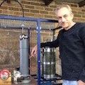
Photos show my primitive glassblowing equipment and a completed discharge bottle so that others may get some ideas. Being that I am not a human lathe, I can't rely on my hands alone to keep two glass tubes coaxial while rotating them and translating them at the same time, so we see the little fixture I made to accomplish this task. The two pieces of tubing are brought together in the jig while rotating in the torch flame, and the springs keep enough restraint on the tubing to keep it coaxial. A finished ion source bottle can be seen on the fixture.
A couple asides now. The best way to cut Pyrex tubing of this size and larger (I have tried many methods!): make a deep but short score mark on the tubing with a carbide knife-sharpener. Wet the score and continue drawing a bit of water about half-way around the circumference of the tube; this is important. Bring a tiny, ultra-hot flame, such as from the #1 tip for this National blowpipe, into brief tangential contact with the tubing a few mm ahead of the score on the DRY half of the tube. The tube will cleanly crack circumferentially on the WETTED side. Finish the job with a gentle tug.
My glassworking torch uses propane from a small $2 bottle (lasts many hours) and oxygen from a 5 LPM medical oxygen concentrator. These concentrators are fascinating but conceptually simple pieces of hardware that exploit the unique affinity of nitrogen for molecular sieve beds. Nitrogen is separated from the air, leaving oxygen and other trace gases. The torch loves it just fine, and you don't have to deal with the expense and nuisance of big gas cylinders.
Thanks to Mike Donovan and local pro glassblower Dean Horinek for their helpful advice on this new skill I'm figuring out.
-Carl
- Attachments
-
-
-
Steven Sesselmann
- Posts: 2128
- Joined: Wed Aug 10, 2005 9:50 pm
- Real name: Steven Sesselmann
- Location: Sydney - Australia
- Contact:
Re: RF ion source, modified, with deuterium (a couple "glassblowing" pics)
Carl,
I like that oxy generator..
By the way, are you getting a brown build up inside the glass tubes after prolonged use?
If so, will it affect the function of the source?
Steven
I like that oxy generator..
By the way, are you getting a brown build up inside the glass tubes after prolonged use?
If so, will it affect the function of the source?
Steven
http://www.gammaspectacular.com - Gamma Spectrometry Systems
https://www.researchgate.net/profile/Steven_Sesselmann - Various papers and patents on RG
https://www.researchgate.net/profile/Steven_Sesselmann - Various papers and patents on RG
-
David Rosignoli
- Posts: 148
- Joined: Thu Mar 04, 2004 9:57 am
- Real name: David Rosignoli
Re: RF ion source, modified, with deuterium (a couple "glassblowing" pics)
Carl,
Nice work. Did you find yourself either pre-heating or post-heating the glass to prevent stress fractures? How did you rotate the glass - by hand? cool stuff.
Dave
Nice work. Did you find yourself either pre-heating or post-heating the glass to prevent stress fractures? How did you rotate the glass - by hand? cool stuff.
Dave
Re: RF ion source, modified, with deuterium
Carl-
Where did you find a 19 mm test tube, either quartz or pyrex? All I can find is plastic. I am trying to dup your gun, with mods, and need only the tube, but I am at a loss.
Thanks,
Charlie Habekost
Where did you find a 19 mm test tube, either quartz or pyrex? All I can find is plastic. I am trying to dup your gun, with mods, and need only the tube, but I am at a loss.
Thanks,
Charlie Habekost
-
Doug Coulter

- Posts: 1312
- Joined: Sun May 27, 2007 3:18 pm
- Real name: Doug Coulter
- Location: Floyd, VA, USA
- Contact:
Re: RF ion source, modified, with deuterium
Boy, I want to see this baby in action, either fusor or beam-target. Great work *again*, Carl!
In my own work, I've found that getting this part right is key to the rest.
As Carl shows (y'all listen up) glass work is all about getting ready -- jigs, the right tools, and even a dry run before anything gets hot are key to success. That's not all that primitive a setup. We use graphite tooling too, and jig blocks, in our case made of that foamy-type kiln firebrick that has almost no thermal mass. Looks like we learned out of the same book.
I'm sure if Carl isn't annealing his work now, he will be at some point. Technique on that varies from just turning off the O2 and coating the piece with soot to using a heat treat oven, and it really helps, as does paying attention to tempcos of the things involved when using unlike materials. I like the oven if you have one available (I do, originally for heat treating steels) and Kohl's book gives all the times and temps for a bunch of materials.
We built a simple thing that lets you put your work between crossed polarizers, with a light source, to see remaining stresses, and it's a great learning tool for anyone getting going. After awhile, you don't need it so much, but at first it's really a help -- and we just used cheapo polarizing film and a CCFL bulb (nice lines in the spectrum make the picture easier to see).
Electrode-less discharges like this are the best it gets in all our testing here. With ECR resonance, we can make ours run down to really low pressures (e-5 mbar and below) for work that wants that -- and need no differential pumping, a bonus. In ours, we let in the gas through the discharge, which may help it run at lower *tank* pressures, as there is some pressure drop between the discharge and the tank proper. Usable pressure differential tends to go up as mean free path does, as in moleclular flow, the gas has trouble getting out of the ion source unless it's ionized and the extractor pulls it out.
At this moment, the original RF source I posted on this forum many months back is still working, no noticeable degradation at all -- it ran yesterday at the flip of the power switch and has needed zero maintenance for a year of running some just about every day. It is the way to go, whatever the implementation details.
Looks like Carl has a real winner here.
Why guess when you can know? Measure!
-
Carl Willis
- Posts: 2841
- Joined: Thu Jul 26, 2001 7:33 pm
- Real name: Carl Willis
- Location: Albuquerque, New Mexico, USA
- Contact:
Re: RF ion source, modified, with deuterium
Hi Charles,
I got my 19mm glass as standard-wall Pyrex tubing from a local scientific glassblower. It can also be ordered online.
19mm test tubes are not as common as some other sizes, but I still have a box of these from eBay auctions. 3/4" is very close...I can't remember if I have used those, but they should probably work.
Good luck, let me know how your ion source turns out.
-Carl
Re: RF ion source, modified, with deuterium
Carl-
Thanks for the tip. I will get some 19 mm pyrez tube and blow a dome.
Charlie
Thanks for the tip. I will get some 19 mm pyrez tube and blow a dome.
Charlie
-
steve_rb
- Posts: 145
- Joined: Sun Oct 18, 2009 4:18 am
- Real name: Steve Robinson
- Location: Tehran University
Re: RF ion source, modified, with deuterium
Spend a few hours trying to do a rough 2D simulation of this Ion source to check how Siglo-2D works. results are attached. Seems at least it can show some sensable results.
- Attachments
-
-
-