Hi all;
just to assure everyone that I am not a transient lurker I am forwarding in the next posting several photo's of my first demo fusor effort. I am within hours of applying vacuum and power. This is my first attempt and my time is limited so I have taken almost a year to get this far. As per an earlier request I will place my photos in a second entry on this thread. More later, Larry Upjohn.
Demo Fusor close to first light
-
Larry Upjohn
- Posts: 135
- Joined: Wed Jan 03, 2007 3:06 pm
- Real name: Larry Upjohn
Demo Fusor close to first light
Larry Upjohn
-
Larry Upjohn
- Posts: 135
- Joined: Wed Jan 03, 2007 3:06 pm
- Real name: Larry Upjohn
Re: Demo Fusor close to first light
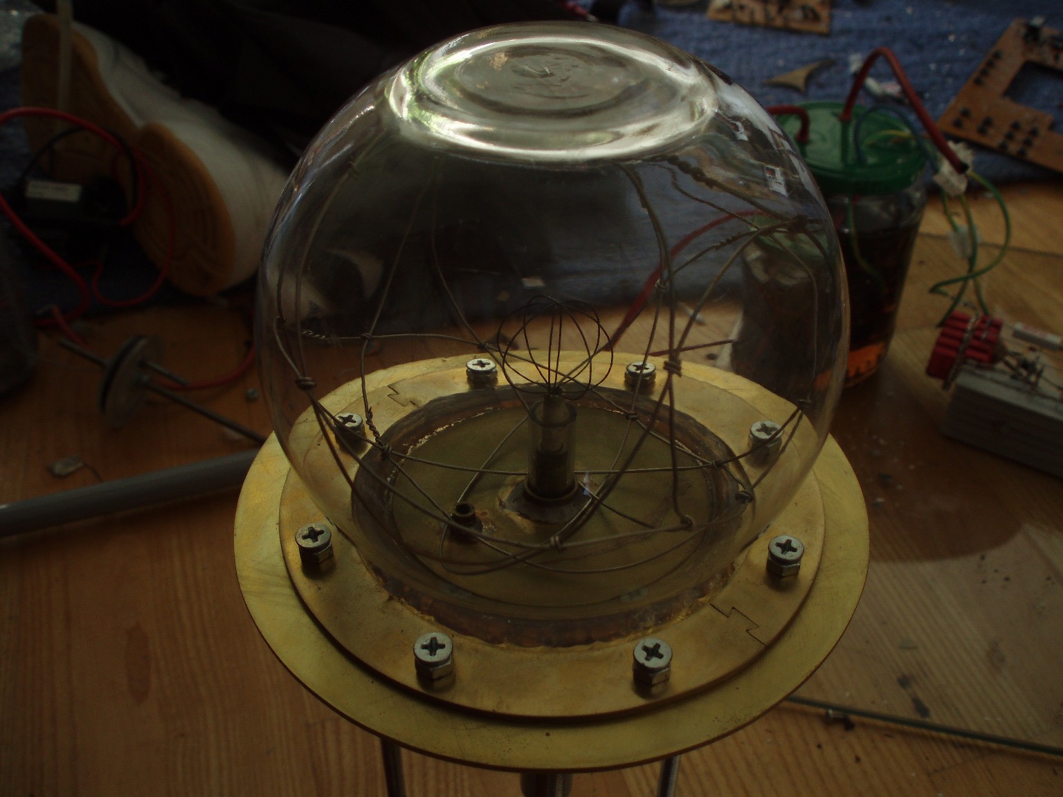
Here are the photo's to document my progress. I am using a new Ford Model A sparkplug for my feedthrough at this stage and a 7500 Volt 60ma old NST wired per Richard's "The Farnsworth/Hirsh Fusor" paper found elsewhere in the Files section for my high voltage supply. Inner Grid is SS 3XX welding wire ( 0.030 inch?) and the outer grid is 2-0 guage copper ground wire. Base plate is a found piece of 7/8" 6061 aluminum and "bell Jar" is the 1/2 gallon fish bowl from Walmart (It is Anchor-Hocking made in USA glass no less) Will have pictures of first plasma shortly. Image 1 is the closeup of the innergrid and feedthrough, outer grid and has a flash reflection which I will learn to get rid of later. Image 2 is a more complete fusor photo sitting on my drill press table ( sorry for the visual clutter, again which will be reduced when operational).
Image 3 is a side on shot of my nearly complete HVDC power supply showing the NST and a home made HV capacitor filter somewhere around 0.5 mfd at 20KV. More later, Larry Upjohn.
Image 3 is a side on shot of my nearly complete HVDC power supply showing the NST and a home made HV capacitor filter somewhere around 0.5 mfd at 20KV. More later, Larry Upjohn.
- Attachments
-
-
-
Larry Upjohn
-
Chris Bradley

- Posts: 2930
- Joined: Fri May 02, 2008 7:05 am
- Real name:
Re: Demo Fusor close to first light
Ensure you have adequate protection around the kit like perspex sheeting, plus eye protection, to catch flying glass and other debris in the event of collapse and/or electron beam spot heating. Best to presume this will happen and to hope that it does not, rather than the inverse.
(if I need to say that! better safe..etc..)
good luck!
(if I need to say that! better safe..etc..)
good luck!
-
Larry Upjohn
- Posts: 135
- Joined: Wed Jan 03, 2007 3:06 pm
- Real name: Larry Upjohn
Re: Demo Fusor close to first light
Chris;
forgot to add that I am using 10" concrete form tubing as a shield with porthole for photos during operation. This is has a 3/8" wall thickness and hopefully it will work for now. I will be replacing the glass "bell-bowl jar" with a unique SS chamber soon but I wanted to get some operational experience with this outfit first. Larry Upjohn
forgot to add that I am using 10" concrete form tubing as a shield with porthole for photos during operation. This is has a 3/8" wall thickness and hopefully it will work for now. I will be replacing the glass "bell-bowl jar" with a unique SS chamber soon but I wanted to get some operational experience with this outfit first. Larry Upjohn
Larry Upjohn
-
Chris Bradley
- Posts: 2930
- Joined: Fri May 02, 2008 7:05 am
- Real name:
Re: Demo Fusor close to first light
Glad to hear it! Safety first. All the best for a successful power-up. Are you running a variac, or is it straight on at nominal full voltage?
-
Larry Upjohn
- Posts: 135
- Joined: Wed Jan 03, 2007 3:06 pm
- Real name: Larry Upjohn
Re: Demo Fusor close to first light
I have a 5 amp variac to ramp the NST up and down as per Richard's schematic. I have used the xformer before in a circuit to provide high frequency high voltage to an arc welder for TIG welding. This was since replaced by a commercial HF unit so the fusor HV power supply is a perfect home for this piece of electrical history. Larry Upjohn.
Larry Upjohn
-
Carl Willis

- Posts: 2841
- Joined: Thu Jul 26, 2001 7:33 pm
- Real name: Carl Willis
- Location: Albuquerque, New Mexico, USA
- Contact:
Re: Demo Fusor close to first light
Looking good, Larry. Should make a very pretty discharge. Your baseplate is sturdy and will support better chambers in the future when the glass fishbowl has "had enough."
I see you are using a lot of NPT / Teflon tape seals in the vacuum line. I have had endless problems with these in vacuum systems, to the point that I usually solder all pipe-thread fittings or epoxy them. At work, if I must make such a connection, I spray the Teflon tape with liquid "VacSeal" resin before wrapping it. That's the only way to guarantee a vacuum-tight joint. Otherwise it's a gamble--fine for small single joints like the 1/8" nipples on thermocouple gauges that are easily redone, but for manifolds with multiple fittings, a big headache in the making.
Good luck!
-Carl
-
Dan Tibbets
- Posts: 578
- Joined: Thu Apr 17, 2008 1:29 am
- Real name:
Re: Demo Fusor close to first light
A couple of 'possibly usefull' comments. I tried a old resistive spark plug as both a feedthrough and limiting resister, using a microwave oven transformer (MOT). It worked, sort of. With the modest vacuums I was obtaining (guessing ~100-200 microns) I had arching to the metal base of the spark plug where the ceramic met the metal. It was old so the surface of the ceramic may have had contaminates that was not as good an insulater as the ceramic itself. I made it work by coating the metal and metal ceramic juntion with several layers of liquid electrical 'tape'. It was ugly, but it worked- till the plug stoped conducting- assume the internal resister burned out.
Also, the tall metal extension may not be ideal as it will also 'glow'. Wraping multiple layers of plumbers teflon tape around it will insulate it some. The tape immediatly next to the glow will melt/fry but should work in a DEMO fuser where you are not concerned about contamination.
Good luck'
Dan Tibbets
-
Dan Tibbets
- Posts: 578
- Joined: Thu Apr 17, 2008 1:29 am
- Real name:
Re: Demo Fusor close to first light
Additional, probably redundant note. In the picture of your NST I do not see a grounding wire attached . Make sure the NST case is well grounded!
And, is your capaciter bank wired is series to increase voltage tolorance of otherwise 'low voltage' capaciters, or are they in parellel to increase capacitance? I don't know the voltage of your NST. Make sure you do not have arching between your capaciter wireing. If the voltage is high enough to arc you may need to embed yor capaciter bank in oil or silicone glue, or hot glue, etc...
Dan Tibbets
-
Richard Hull

- Moderator
- Posts: 15028
- Joined: Fri Jun 15, 2001 9:44 am
- Real name: Richard Hull
Re: Demo Fusor close to first light
Good luck with first light.
Richard Hull
Richard Hull
Progress may have been a good thing once, but it just went on too long. - Yogi Berra
Fusion is the energy of the future....and it always will be
The more complex the idea put forward by the poor amateur, the more likely it will never see embodiment
Fusion is the energy of the future....and it always will be
The more complex the idea put forward by the poor amateur, the more likely it will never see embodiment
-
Larry Upjohn
- Posts: 135
- Joined: Wed Jan 03, 2007 3:06 pm
- Real name: Larry Upjohn
Re: Demo Fusor close to first light
Thanks to everyone for your thoughtful input. My powersupply is only partially wired so the ground through the ammeter is not evident. The caps are wired in parallel and as noted were in a circuit with a sparkgap to provide highfrequency high voltage AC coupled to an arc welder output for "cheep" no touch TIG arc starting. It did not arc over in that application so hopefully will not arc in DC mode. BTW I have dremeled off most of the unecessary copper on the backside of the board to prevent arching. The stalk will be insulated with ceramic tubing when it arrives. The teflon plumbers tape is an admitted cludge. I will probably retain it only on the base joint, the TC guage coupling. I will probably seal the remainder using silphos or silver bearing solder. If nothing else I hope my efforts lead to reproducing the fusor experiment. I am after all standing on some tall shoulders here. Larry Upjohn.
Larry Upjohn
-
Larry Upjohn
- Posts: 135
- Joined: Wed Jan 03, 2007 3:06 pm
- Real name: Larry Upjohn
Re: Demo Fusor close to first light
Tonight after a flight home from Seattle I have applied voltage for the first time. Vacuum is noted on the photos below. The lowest is just chamber pump down with no power to the grid. The second guage photo represents pressure increase with grid power. First two grid photos are the early scintillation noted when power applied. This started to appear when the voltage was around -1100 volts. My ammeter circuit is not working as connected so will need to revise it to a properly shunted analog ammeter movement. Final photos are of the grid glow. Got several beams which heated inner grid on one side to redness with formation of distinct intense blue plasma inside the grid. I switched off the variac to avoid melting grid or glass globe. Finally I ran the power at a lower level, scintillation gradually disappeared and glow seemed to focus inside inner grid. No finally focused poissor appeared but this is only my demo plasma to begin with and I shut everything down for the night. The glass globe is now nicely coated with a deposition looking similar to carbon that we used to coat transmission electron microscope samples with. Glass was slightly warm on the side of the grid that got incandescant. No radiation instrumentation used as total voltage never exceeded -4.5kv. I appologize for the quality of the photos as taking pictures and keeping clear of the HV in the relative dim lighting was enough to handle right now. More later, Larry Upjohn.
- Attachments
-
-
-
-
Larry Upjohn
-
Steven Sesselmann

- Posts: 2128
- Joined: Wed Aug 10, 2005 9:50 pm
- Real name: Steven Sesselmann
- Location: Sydney - Australia
- Contact:
Re: Demo Fusor close to first light
Larry,
Congratulations on first light!
I am no expert on regular Farnsworth fusors, but to me it looks as if your vacuum gauge is showing a better vacuum that you are achieving.
Some of the other guys might confirm this, by the appearance of the plasma.
Steven
Congratulations on first light!
I am no expert on regular Farnsworth fusors, but to me it looks as if your vacuum gauge is showing a better vacuum that you are achieving.
Some of the other guys might confirm this, by the appearance of the plasma.
Steven
http://www.gammaspectacular.com - Gamma Spectrometry Systems
https://www.researchgate.net/profile/Steven_Sesselmann - Various papers and patents on RG
https://www.researchgate.net/profile/Steven_Sesselmann - Various papers and patents on RG
-
Richard Hull
- Moderator
- Posts: 15028
- Joined: Fri Jun 15, 2001 9:44 am
- Real name: Richard Hull
Re: Demo Fusor close to first light
Larry, Your name is added to the plasma club listing.
Nice first light. This is always a major moment
Richard Hull
Nice first light. This is always a major moment
Richard Hull
Progress may have been a good thing once, but it just went on too long. - Yogi Berra
Fusion is the energy of the future....and it always will be
The more complex the idea put forward by the poor amateur, the more likely it will never see embodiment
Fusion is the energy of the future....and it always will be
The more complex the idea put forward by the poor amateur, the more likely it will never see embodiment
-
Larry Upjohn
- Posts: 135
- Joined: Wed Jan 03, 2007 3:06 pm
- Real name: Larry Upjohn
Re: Demo Fusor close to first light
Steve;
I have already budgeted a Baratron style capacitance manometer for my "real" harder vacuum guaging. This TC sending unit has been rehabed after oil contamination so it a qualitative guage right now till the Baratron is on board. More later, Larry Upjohn.
I have already budgeted a Baratron style capacitance manometer for my "real" harder vacuum guaging. This TC sending unit has been rehabed after oil contamination so it a qualitative guage right now till the Baratron is on board. More later, Larry Upjohn.
Larry Upjohn
-
Larry Upjohn
- Posts: 135
- Joined: Wed Jan 03, 2007 3:06 pm
- Real name: Larry Upjohn
Re: Demo Fusor close to first light
Thanks Richard. There is much more to do, starting with a cleanup of my limited work space, improvement of my project realization and etc. I am still working two jobs so time is much at a premium as well. I am threatening to retire to just one job here soon. More later, Larry Upjohn.
Larry Upjohn
-
Larry Upjohn
- Posts: 135
- Joined: Wed Jan 03, 2007 3:06 pm
- Real name: Larry Upjohn
Re: Demo Fusor close to first light
Have refined the Demo Fusor to eliminate the Glass Globe. I replaced the silver soldered inner grid as well. I managed to deposit molecular silver over the interior of the globe internal components including the insulator of the Sparkplug. It cleaned right up with silver polish. Inner grid is all stainless now with an thick walled aluminum pot serving as the bell jar now. Larry Upjohn.
Pictures include the new chamber, new inner grid and yellow teflon tape I have found that seals NPT fittings quite well.
Pictures include the new chamber, new inner grid and yellow teflon tape I have found that seals NPT fittings quite well.
- Attachments
-
-
-
Larry Upjohn
Re: Demo Fusor close to first light
How did you make that beautiful inner grid?
Re: Demo Fusor close to first light
Larry -
Nice work!. I was also going to compliment you on the beautifully done inner grid. A definite work of art!
My only caution is about your ball valve on the vacuum line (unless I've misunderstood what I see). The in- line seal around the ball is probably fine for these purposes, but I wondered about the stem seal, it could leak enough to add to your residual gasses.
Dave Cooper
-
Doug Coulter

- Posts: 1312
- Joined: Sun May 27, 2007 3:18 pm
- Real name: Doug Coulter
- Location: Floyd, VA, USA
- Contact:
Re: Demo Fusor close to first light
Very nice, this is a great start!
I admire your cool grid as well, but here haven't had much luck with spirals, for whatever reasons, I've not pursued them. I'm the cylinder grid guy here.
What struck me right off is the use of the sparkplug backwards -- that's smart. It can be real hard to keep a discharge happening on the other end in low pressures indeed, and hard to fix once it's happened, the long insulator in the vacuum is the way to go for sure.
It is getting tough to find non resistor plugs, and the ones that have like 10k R in them burn out very easy, especially the way yours is -- no good way for heat to get out. BillF found us some really really old ford plugs, like for model T or something, that not only have no R but are simply huge on both ends (Standard NPT on the engine side as a bonus) and for those I was able to find some ceramic tubing to extend the insulator on the "inside" side after welding (not brazing) a longer wire to it, and it's still in service on his machine as a feedthrough for the ion source.
I used an oldie but goodie glue formula for that -- sodium silicate with talc made into a slurry. It gets hard like epoxy, but it takes a looooong time, as in a few days to do so. A few more days at sub boiling heat and the water if finally gone and it will then stand yellow heat, and sticks really well to these things. If you heat it too soon -- it goes bang, the hardening process is not the same as getting the water out.
Why guess when you can know? Measure!
-
Larry Upjohn
- Posts: 135
- Joined: Wed Jan 03, 2007 3:06 pm
- Real name: Larry Upjohn
Re: Demo Fusor close to first light
Hi All;
I have not quite kept up with my development schedule due to few extra fusor minutes. I have been continuously pumping my chamber now fitted with both a TC gauge and a 15 torr Baratron capacitative manometer. I have done an Excel spreadsheet to sort out my observations and see how the two gauges correlate. I have noticed an interesting effect as the ambient temp goes down (unheated garage area) the vacuum indication creeps upwards. I suspect it is a complience issue with the base gasket material (red rubber gasket) and as noted the teflon in the ball valves probably including the shaft packing as noted earlier. I have now collected three pneumatic bellows valves and will build them into the "real" fusor system. By the way thanks for the observations on the grid. The following thread:
viewtopic.php?f=6&t=2863&hilit=shaker#p12373
was my inspiration. I picked up the shaker bottle at GNC for around $8.00USD. This is clamped to a SS bolt threaded on the other end to the Sparkplug. This is
a non-resistor Model A Ford sparkplug (new) from Antique Ford Parts of Sacramento.
They have a website and these can be ordered online for around $4.00USD. The plug is a standard 1/2" NPT thread. Thanks again for your encouragement. I will keep plugging away.....Larry Upjohn.
Larry Upjohn
-
John Futter
- Posts: 1850
- Joined: Wed Apr 21, 2004 10:29 pm
- Real name: John Futter
- Contact:
Re: Demo Fusor close to first light
Two modern sparkplugs with no internal resistor come from NGK
standard size D7EA
small size (approx 10mm thread) C7HSA
We use dozens of these @ work on ion sources and implanters.
We have a test setup for the leak detector to test them--- none have leaked --so now we just take one out of the box and use it without testing
Edit
you can select what you want from here --just avoid the R type plugs from NGK
http://www.ngk.com/sparkplug411_manufac ... cturerID=1
-
adrian.f.h
- Posts: 39
- Joined: Tue Feb 17, 2009 1:04 pm
- Real name:
Re: Demo Fusor close to first light
Nice effort!
I think the first post in this set was made when I had my first success on demo fusors. Sort of inspiration for my first tests as can be seen on this picture http://www.adrian-homelab.de/bild55.JPG from my website.
I use sparkplugs too but with the plug facing in. But using them the other way seems to be even better regarding isolation and the connection with the inner grid. On the outside of the chamber epoxi seals are not such a problem. Some are using epoxies in their vac system and I do so for an improvised flange connection on the rotary pump but I personally don't trust them especially when the chamber becomes fairly hot during operation.
This spurkplug thing is by far one of the most professional low cost improvised feed through solutions I found.
I'm really interested what's the maximum voltage rating, as I never heard of failures?
-
Richard Hull
- Moderator
- Posts: 15028
- Joined: Fri Jun 15, 2001 9:44 am
- Real name: Richard Hull
Re: Demo Fusor close to first light
The spark plug useage goes back to my fusor I and fusor II in 1997. They do indeed fail once voltages rise to what anyone might consider "useful levels". For demo only fusors, they are quite servicable, but that is pretty much their limit.
I did do my first low level, moderately detectable fusion in 1998 using a spark plug in fusor III, but within days, it arc'd over and that was that.
Much discussion on this can be found in the old songs forums. The spark plug more or less dropped from sight in fusor construction until just recently.
Richard Hull
Progress may have been a good thing once, but it just went on too long. - Yogi Berra
Fusion is the energy of the future....and it always will be
The more complex the idea put forward by the poor amateur, the more likely it will never see embodiment
Fusion is the energy of the future....and it always will be
The more complex the idea put forward by the poor amateur, the more likely it will never see embodiment
-
Doug Coulter
- Posts: 1312
- Joined: Sun May 27, 2007 3:18 pm
- Real name: Doug Coulter
- Location: Floyd, VA, USA
- Contact:
Re: Demo Fusor close to first light
That's good info John, thanks. We'd only found the super old and hard to find Ford plugs so far.
I have also had decent success with just sealing a thick wall ceramic tube through a hole in a CF flange with Hysol, as long as it doesn't get too hot, it's fine, and should you need to, you can smash the ceramic back out and replace it. Cheezy but functional.
For real high volts though, it's hard to find a thick enough walled piece of ceramic, which is why the pro HV FT's are made the way they are -- a long very open space on the inside, so at no point does the wall thickness alone have to stand off the full volts. In a fusor, with space charges etc I've had troubles with these though, and now use my own design with quartz tubing, which at least is cheap by comparison to replace should you need to. (ten bucks for a new piece of quartz vs the cost of a new 50-100kv FT looks real good to me).
Why guess when you can know? Measure!