My fusor is ready and yesterday I succeed on creating my first plasma but color in not pink as it should be. It is more like blue (a bit to light side) and a little purple too. D2 gas is pure (99.999) as it says on the sticker on the bottle. Bottle was stored for about 2 years in the atmosphere though. Pressure is 100 Bar. Using two stage Harris regulator. Before letting D2 in I had 3E-6 vacuum inside my Pyrex chamber (I have Ti coated on Al target inside the chamber connected to 50 Kv but voltage not turned on yet plus 13.56 MHz RF generated plasma in quartz chamber). I let D2 into quartz chamber until vacuum reached about 3E-3 in the whole system and plasma ignition was OK. Before connecting HV I need the right color of plasma to generate neutrons.
Plasma chamber is Quartz and will keep at about 1E-3 but target chamber is Pyrex and will keep it at about 2E-6 during neutron generation. Between these two chambers is a metal cone with about 0.7 mm aperture for ions passage to the target. I am hoping this aperture and turbo pump I am having to be able to maintain this pressure difference.
Tubing from D2 Cylinder to chamber is about 3 meter and didn't do any cleaning. Could it be because tubing or chambers are dirty and need cleaning? If so how should I clean them?
Plasma color problem for neutron production?
-
Jerry Biehler
- Posts: 975
- Joined: Tue Nov 24, 2009 3:08 am
- Real name:
- Location: Beaverton, OR
Re: Plasma color problem for neutron production?
Dont rely on color from a posted web image. Many cameras render color differently and are more or less sensitive to IR than others which throw off the color balance. Once with cheap IR filters will look more pink.
That being said, were all the lines purged for the D? If the lines are metal turn off the valve at the regulator and let the lines go to vacuum. You can also help outgassing by heating up the lines and fitting with a heat gun.
D wont go bad in a tank.
That being said, were all the lines purged for the D? If the lines are metal turn off the valve at the regulator and let the lines go to vacuum. You can also help outgassing by heating up the lines and fitting with a heat gun.
D wont go bad in a tank.
-
Chris Bradley

- Posts: 2930
- Joined: Fri May 02, 2008 7:05 am
- Real name:
Re: Plasma color problem for neutron production?
steve robinson wrote:
> My fusor .... Pyrex chamber (I have Ti coated on Al target inside the chamber connected to 50 Kv but voltage not turned on yet plus 13.56 MHz RF generated plasma in quartz chamber)... Plasma chamber is Quartz ... Between these two chambers is a metal cone with about 0.7 mm aperture for ions passage to the target.
This isn't a 'fusor' in the conventional interpretation. As you do not yet appear to have turned on a voltage to accomplish a DC glow discharge, and it is not a fusor, and there are two chambers, and they are non-metallic, and there is a target and some ion focussing, then there are a heap of details (and probably more) behind your question to which I hope you will realise any answers would be guesswork.
The classic dominantly 'Balmer Alpha' pinky colour is a typical sight in a typical fusor. It is not impossible to gain a bluer colour in a hydrogen discharge from the other Balmer spectral emission lines under different conditions. Similarly, residual, or leaking, gases may be the cause.
I have generated spectra by buying a very cheap diffraction-film based spectrometer and photographing the resultant spectrum through it. You could do the same, then you will see if they are indicative of a higher proportion of shorter wavelength Balmer lines, or of contaminations. Examples are given below. The scale is imperfect, but to be fair the item did come with a hand-written sticker on the top marked '~+20nm'. One can hardly quibble with that accuracy for a $5 instrument given its actual errors are around +30nm for long wavelengths, +20nm for middle, and +10nm for short! Some additional modification was required to the slit, namely, it had to be narrowed to gain finer resolution on the lines.
For experimentation which deviates away from the fusor norm, it seems inevitable to me that some means for spectral confirmations of the gasses that may, or may not, have been excited is an inevitable experimental requirement. In my case, this was to understand what was, or was not, happening within my epicyclotron device which, as it happens, also appears to tend to run a 'bluer' Balmer series of emissions than a conventional fusor (viz. the Balmer beta emission appears to present proportionately more strongly).
I have to flag up, too, a question regarding how you are using RF to excite a plasma in a pyrex/quartz vessel? Please bear due regard to what high power RF can do where it is not contained in a suitable wave-guide.
- Attachments
-
-
steve_rb
- Posts: 145
- Joined: Sun Oct 18, 2009 4:18 am
- Real name: Steve Robinson
- Location: Tehran University
Re: Plasma color problem for neutron production?
I used Cu coil around a 3 cm x 5cm quartz tube (chamber) and seems I am getting the first 5 lines of Balmer series. But red line is missing which I think my RF is not strong enough (low Peak to peak voltage) to excite D electrons to higher levels to emit red line spectra.
I have a question: I need D to get ionized and some of these ions to escape from teared deby layer in the vicinity of the exit hole and accelerate towards the target before getting recombined. This means the longer recombination time is preferred. Anyone knows recombination times of these Balmer lines? Probably the Balmer Alpha should be longer than the other lines, right?
I have a question: I need D to get ionized and some of these ions to escape from teared deby layer in the vicinity of the exit hole and accelerate towards the target before getting recombined. This means the longer recombination time is preferred. Anyone knows recombination times of these Balmer lines? Probably the Balmer Alpha should be longer than the other lines, right?
-
Chris Bradley
- Posts: 2930
- Joined: Fri May 02, 2008 7:05 am
- Real name:
Re: Plasma color problem for neutron production?
steve robinson wrote:
> seems I am getting the first 5 lines of Balmer series. But red line is missing which I think my RF is not strong enough
The red emission is the lowest energy emission. To get the UV content the hydrogen needs to be very highly excited.
What is your basis for suggesting you are getting Balmer series emissions?
steve robinson wrote:
> Anyone knows recombination times of these Balmer lines?
The question makes no sense. The cross-section for recombination varies on particle energy. Assume 10^-15-10^-16cm^2 would not be unreasonable.
-
Jim Kovalchick
- Posts: 717
- Joined: Wed Apr 13, 2011 8:00 pm
- Real name:
Re: Plasma color problem for neutron production?
Steve,
When I saw your post it reminded me of some similar questions my son Mike had last year about his fusor conditions. I think he got a suggestion here about the camera infrared sensitivity to use a remote control to see if his video was suceptible. I can't remember what color showed up, pink or blue, but I do remember that the camera could see a tv remote control when a human eye couldn't.
Here's a link to a thread Mike started about a subject similar to your question.
viewtopic.php?f=6&t=3177&hilit=light#p12687 spectrum
good luck,
Jim K
-
Carl Willis

- Posts: 2841
- Joined: Thu Jul 26, 2001 7:33 pm
- Real name: Carl Willis
- Location: Albuquerque, New Mexico, USA
- Contact:
Re: Plasma color problem for neutron production?
Hi Steve,
It is hard to know what your system is supposed to look like with pure deuterium gas. Glow discharges have different regions, characterized by different electron velocities and different excited species. In a typical fusor at ~10-50 mtorr, with a DC field, one sees a deep reddish color in deuterium gas. But if you fill the vessel to a much higher pressure, say 2 torr, you will start to get the bright bluish-white negative glow. At still higher pressures, you can expect to see the emergence of the "positive column" plasma. RF plasmas at a few mtorr in my ion sources always look bluish-white, while the extracted beam appears deep red if there is significant residual gas in its path.
Hydrocarbons impart a deep bluish color to a discharge at high pressures, and the characteristic color is valuable sometimes when hunting leaks. Air looks pink at these same pressures. Deuterium will likely look bluish-white.
If you question the purity of the gas, you should probably assess whether or not you have leaks. Valve off your system and see if the pressure rises quickly. Spray alcohol on your fittings and see if the pressure rises and the discharge turns dark blue. Etc.
-Carl
-
steve_rb
- Posts: 145
- Joined: Sun Oct 18, 2009 4:18 am
- Real name: Steve Robinson
- Location: Tehran University
Re: Plasma color problem for neutron production?
H-Alpha paper from Wikipedia says "H-alpha has a wavelength of 656.281 nm. Since it takes nearly as much energy to excite the hydrogen atom's electron from n = 1 to n = 3 as it does to ionize the hydrogen atom, the probability of the electron being excited to n = 3 without being removed from the atom is very small. Instead, after being ionized, the electron and proton recombine to form a new hydrogen atom. In the new atom, the electron may begin in any energy level, and subsequently cascades to the ground state (n = 1), emitting photons with each transition. Approximately half the time, this cascade will include the n = 3 to n = 2 transition and the atom will emit H-alpha light. Therefore, the H-alpha line occurs where hydrogen is being ionized." (source : http://en.wikipedia.org/wiki/H-alpha).
That is what I want: Ionized D gas in the plasma. This means I need to give enough energy to electrons to excite them from n=1 to n=3 which is equal to the ionization energy. As it says in the last line H-alpha occurs where Hydrogen is being ionized. Now question is what kind of RF do I need for making ionization maximum?
That is what I want: Ionized D gas in the plasma. This means I need to give enough energy to electrons to excite them from n=1 to n=3 which is equal to the ionization energy. As it says in the last line H-alpha occurs where Hydrogen is being ionized. Now question is what kind of RF do I need for making ionization maximum?
-
Doug Coulter

- Posts: 1312
- Joined: Sun May 27, 2007 3:18 pm
- Real name: Doug Coulter
- Location: Floyd, VA, USA
- Contact:
Re: Plasma color problem for neutron production?
Here is some very pure D (checked with a mass spec) under some various conditions. It color-renders very close to what my eye saw at the time, with some minor caveats. At the focus of my main grid, there's enough IR to fool the camera a little and make it look a little whiter than the usual "purple" color I see. What you see is dependent of course on your computer monitor, your own eyes (not everyone has the same color vision), and the other conditions. For example, this shows a secondary grid I use as an ion source at low power density - and the color is a little different than the rays or focus of my main grid, in real life, and on camera. Here you can also see the light blue fluorescence in the side feedthrough (quartz) and the red fluorescence of the fish beads (alumina) feeding the ion source grid.
Remember, as D cascades down the energy levels, light from the UV continuum on down is generated, not just the red line. The result looks a lot like purple to my eyes.
http://www.youtube.com/watch?v=Us7Ma230huY
Remember, as D cascades down the energy levels, light from the UV continuum on down is generated, not just the red line. The result looks a lot like purple to my eyes.
http://www.youtube.com/watch?v=Us7Ma230huY
Why guess when you can know? Measure!
-
steve_rb
- Posts: 145
- Joined: Sun Oct 18, 2009 4:18 am
- Real name: Steve Robinson
- Location: Tehran University
Re: Plasma color problem for neutron production?
Doug
Great video. I am a little confused about the number of grids you have used and HV connection to grids. Could you please send a hand drawn schematic showing your system with grids and HV connection with the amount of HV written when you had counts.
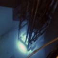
I have attached my first D2 plasma with out Ti target yet. Just an aluminum cap instead of the target you can see in the photo. Soon I will replace it with the target and see if I can get any count on my Eberline ball neutron detector with BF3 prob.
Great video. I am a little confused about the number of grids you have used and HV connection to grids. Could you please send a hand drawn schematic showing your system with grids and HV connection with the amount of HV written when you had counts.
I have attached my first D2 plasma with out Ti target yet. Just an aluminum cap instead of the target you can see in the photo. Soon I will replace it with the target and see if I can get any count on my Eberline ball neutron detector with BF3 prob.
- Attachments
-
-
Richard Hull

- Moderator
- Posts: 15032
- Joined: Fri Jun 15, 2001 9:44 am
- Real name: Richard Hull
Re: Plasma color problem for neutron production?
Steve, You have been entered into the plasma club. Welcome and we look forward to future reports on your progress.
Richard Hull
Richard Hull
Progress may have been a good thing once, but it just went on too long. - Yogi Berra
Fusion is the energy of the future....and it always will be
The more complex the idea put forward by the poor amateur, the more likely it will never see embodiment
Fusion is the energy of the future....and it always will be
The more complex the idea put forward by the poor amateur, the more likely it will never see embodiment
-
Doug Coulter
- Posts: 1312
- Joined: Sun May 27, 2007 3:18 pm
- Real name: Doug Coulter
- Location: Floyd, VA, USA
- Contact:
Re: Plasma color problem for neutron production?
I chose that vid because it displayed the color well, it was not a typical (or great) run or anything special otherwise. Your pic doesn't look bad - you're close to if not at decent purity.
Don't have time to draw just now, but this was pretty simple. I'm running my main grid in a 6" sidearm off a 14" by 26" tall main tank, with the open end of the cylinder grid pointing out into the main tank, HV coming in from behind. That one is driven by a Spellman SL2KW 50kv/40ma supply which is usually loafing - through a 50k ohm WW ballast resistor 13" by 1" diameter, forced air cooled in a tube, shielded for EMI reasons (and safety). That ballast is on the low side - it mainly works well once a grid has been "conditioned", else it allows for too much peak current during conditioning sparks - for a new grid, double that (100k) till it is broken in. My main grid is (in general, this is something I change) 8 rods 2" long equal spaced around the edges of 1" ends - about 7/8" OD for the grid rods. The end is "open" graphite ring with a 3/4" hole in it - a smaller hole there both increases waste heat and reduces neutron output. Still fooling with materials for the back end - have tried graphite but it sputters onto my HV FT insulator, so right now it's Ti, anodized, to reduce secondary electron emission. The rods are tungsten TIG welding rods cut to length on a diamond saw. I've used .040 and .020 (hard to find) diameter rods. It hasn't made a big difference whether those rods are Th, La, Y doped or not. Ti also works well for grid wires, but you can melt it easier if you get cowboy on the power input - the Spellman would make a pretty decent arc welder - it's about the same power level if you want it, but usually, you don't, things just melt.
My "ion source" grid is 1" by 1" 6 wire "cylinder" made of all tantalum (playing with materials again), nothing special, not very precise as Ta is so malleable it's hard to make things perfectly straight. It's out in the middle of the main tank, a little off to the side because of mechanical and viewing considerations. It is fed by a Spellman (I really love these things) 40kv/12.5ma supply, and is most often run in current limit at around 10kv under the gas conditions I use, with a similar but 100k ohm ballast. In fact, the voltage at which it hits current limit is by far a more sensitive indicator of the gas pressure than the gage.
Due to Paschen's law, this grid will "light off" at lower gas pressures and voltages than the main grid, and can be used in similar fashion to a control grid in a triode to turn the main grid on and off. Some conditions have a non-monotonic response for this. For the little grid, pxd is larger for the same p, since it's out in a larger space, which is why it shows this characteristic. I've used other ion sources that worked well, it's just that this one is super simple and reliable.
I start to see counts definitely out of the noise at a mere 16kv or so. The count rate goes up more or less exponentially with voltage up to my limit of about 53kv (Spellmans are conservatively rated).
I'd expect to need a bit more in a linac, as there won't be any head on collisions with both particles at the supply voltage velocity - the ones in the target are stationary.
I'm told that loading up a Ti target is problematic in some cases. If there's any O or N on the surface, it's hard to get the D to go into it. When I coated my sidearm walls with D absorbing stuff (I've tried Pd and Ti, and like Ti better - fewer X rays and holds the D to higher temps), there wasn't a time it was exposed to atmosphere before I loaded it up with D, and it was quite thirsty as a super-clean surface - I let in some D, and it just sucked it up, cold, lots of it. According to Phillips, a thin Ti coating on a target (over something that D doesn't diffuse well into, like gold or silver) works better than bulk sheet Ti. I have not yet parameterized that one myself.
I think when Carl tried a variation of this he used a Ti bolt head, but had mixed results due to low absorption of D in that - maybe he can chime in with more. I know Ti that's been out in air awhile does not absorb much D and isn't embrittled like very clean Ti is. TiN or TiO(n) doesn't get reduced chemically by hot/fast D, else Ti would be cheap, so you can't just (easily) overcome that one. You might be able to sputter off a layer, but then you've got a mess of sputtered Ti around the rest of the thing.
You can find a lot more on my youtube channel: http://www.youtube.com/user/DCFusor
Or on my forums: http://www.coultersmithing.com/forums/index.php
Look under the nuclear sub-forum there. What I do is take vids, put them on youtube, and embed them in the forums, which is where the explanations are.
I use a PKR-251 gage, which reads a little off with pure D, so I'm a little reluctant to give absolute gas pressures (I have to do some math to get to that, assuming their calibration chart is true, it's reading almost a factor 2 higher than truth on D), but it reads in general 1.6 to 2.2 e-2 millibars on good runs, depending on other things I'm trying at the time. I generally run in a batch type of mode - starting from "hard" vacuum (e-9 millibar!) I fill the tank to around that pressure with D, valve off my forepump from the turbo, and run. During a run I can let in little slugs of D via a solenoid valve/orifice, or take out gas via a solenoid valve between the forepump and turbo. I spin the turbo way down to make that slow enough to be easy to control, just at the speed where it doesn't pump D very well, but does pump heavier gases very well - it acts as a D purifier. That would be in the 250-400 rps range on a turbo that nominally spins 833 rps (6" 512 l/s pump).
In fact, due to the V-I properties of a fusor, it's more accurate and repeatable to just get in range with the gas pressure and adjust gas pressure while watching the supply voltage and current. A change that doesn't even show or only flips one digit on the 3 digit DPM readout is just about the entire usable range for the fusor.
A linac is going to be different for most of this.
Why guess when you can know? Measure!
-
steve_rb
- Posts: 145
- Joined: Sun Oct 18, 2009 4:18 am
- Real name: Steve Robinson
- Location: Tehran University
Re: Plasma color problem for neutron production?
I am trying to maintain a pressure difference between plasma chamber and target chamber. Target will be connected to about 50Kv. At this voltage target chamber should be at about 1E-5 to 1E-6 to prevent spark. But plasma need about 1E-1 to 1E-3 in order to be turned on using RF power. I have to have about 1 mm diameter orifice between these two chambers according to text books for Deby layer to allow ions get out of the orifice towards the target. My problem is how to maintain this pressure difference while having an orifice at such a large diameter? Any ideas?
This is the point that capillary should act by decreasing the D gas flow to a very low level but still don't know how to calculate the flow rate between two chambers in order to maintain this pressure difference?
I have to calculate how much gas should flow from a chamber at let say 1E-2 pressure to the chamber at 1E-6 pressure through the 1mm diameter orifice. If D from cylinder turned off the flow in the orifice will cause both chambers will have the same pressure after a short time but if exactly the same amount of gas which are flowing through the orifice enters the 1E-2 chamber and also exactly the same amount of gas gets out of the 1E-6 chamber this pressure difference will be maintained between the two chambers. Could someone expert in gas dynamic help with this orifice flow calculations? I am not good in gas dynamic and once searched but couldn't find useful information.