Hi everyone. I've been a lurker here for a while - I probably visited after discovering UW's program back early in the decade, but got really into fusors after watching Dr. Bussard's talk (several times). I'm just finishing grad school and my life is starting to settle to the point where I'd like to get hands on and start tinkering with my own in the next year or so.
I've seen a lot of fusors being built on this forum, but mainly with grids. Have any of the amateurs attempted a polywell? This piques my curiosity, and is a bit different.
My bachelor's is in EE, although I never really used it for anything but hobbies. My masters will be Aerospace. My hobbies go more towards wooden crafts, but I have a basic machine shop at my work that I can use on weekends and I have a good amount of experience on drill presses, saws, and oxyacetylene torches. In other words, I know there are plenty of gaps in my experience, but I think I can do this.
I have a basic conceptual design worked out - to keep it simple, I've decided to go with the continuous pipe approach that EMC2 used in the MG machine. My goal for this version is plasma, I don't expect fusion.
I'll probably make the first magrid from stainless, to allow me to run it on easier-to-find power supplies, and so that it will take a heating and a beating from what will no doubt be lots of bending, power surges, and good ol' fashin rasslin' into place. I won't cool it at first, but it will be possible with this setup to cool it with water. Not sure where to go for a good low voltage PS, but I've seen a few threads on that in these forums and we've got a good surplus store in town, so I'll start there.
I'm thinking I'll just do a Lexan dome for the vacuum chamber, and use a resin injection pump, which should be able to get it well under 1 mbar.
The area that I have no idea about is the electron source. Can I use the gun from a CRT or is this a bad place to start? Remember I'm just looking to make a fuzzy glowing ball at this point - the hope being I'll learn enough about everything to make fusion next time.
My questions -
I'm sure there's at least one "is he crazy?" statement in there. So please feel free to point it out with colorful language.
I'm at a point right now where I think the next move is to build something, but I want to avoid wasting money as much as possible (see above re: grad student). I get enough calculating at work and school, and I'd like to make this as empirical as possible - but what can I absolutely not get away with fudging here? Meaning, what kinds of things have cost people months and hundreds to thousands of dollars on a forehead-slapper after they finally did calculate something and realized it would never work?
I did a search and didn't find anything - has any of you attempted a polywell design before? I see mostly double-screen designs in this forum.
Thanks everyone!
Amateur polywell?
Re: Amateur polywell?
I'd like to have a go myself after I get a fusor working.(My particular interest is in permanent magnets and whether they can play a useful role or not.) I don't know if your aware, but you might find this forum particularly useful in that direction:
http://www.talk-polywell.org/bb/index.php
Progess for me is slow due to lack of time and funds, but I have noticed so far that the more money you have, the less time you need
Having plenty of space to build is a good thing, and as many friends with skills to help wouldn't go amiss either.
And spending litterly months reading all the previous forum posts and making notes will help a lot more than you might think.
Ebay can be a useful source for parts.
-
Chris Bradley

- Posts: 2930
- Joined: Fri May 02, 2008 7:05 am
- Real name:
Re: Amateur polywell?
What is your motivation for doing a 'demo' Polywell? The issue is that you WILL get a plasma if you zap a big enough ion/electron gun into just about any micron-evacuated device, whether or not you've scattered magnets around inside it, randomly or otherwise. So you will need to identify your 'end-point', that is, how will you know if your experiment is 'Polywell-ing' and confining electrons?
Re: Amateur polywell?
Dude, what kind of question is that? The guy wants to do it because it's COOL, yeah....!!
Because it gives him bragging rights. Who knows, who cares, just let people do what they do in their time with their money. At least it's better than making a model plastic airplane.
My friends at the University of Illinois IEC program used to ask the same question about the Fusor forum people, they thought our time would be better spend making liquid rocket engines and I told them the same thing I'm telling all of you, we do it because it's COOL and Fun.
No other reason needed, but feel free to add your own.
Peace.
-
Chris Bradley
- Posts: 2930
- Joined: Fri May 02, 2008 7:05 am
- Real name:
Re: Amateur polywell?
...because I'd like to see him have bragging rights over something more than just a bright light if he's going to put that much effort into something. Just a bit of experimental and instrumentation planning on day one may help, with a little bit of upfront discussion!
I could get a plasma-ball-toy from the shop and put a half-dozen magnets around it to make it look like a Polywell. That hardly means I've done anything of merit towards an amateur Polywell, does it? I understand the point of posting here *prior* to a proposed experiment is to encourage some dialogue to progress the idea. If there is no discussion wanted, then just do the experiment and *then* post with results!
Bragging rights come with posting results. But bragging rights aren't like 'futures', you can't claim them now then cash them in later. Speculative forward-bragging doesn't get much respect here, but it may generate a 'healthy' discussion!
Re: Amateur polywell?
Hey I'm all for that, just don't bring the guy down, that was my point.
-
Chris Bradley
- Posts: 2930
- Joined: Fri May 02, 2008 7:05 am
- Real name:
Re: Amateur polywell?
Sorry. I seem to be coming across in 'hardball' mode these days.
Re: Amateur polywell?
It's cool. It happens to all of us.
-
Carl Willis

- Posts: 2841
- Joined: Thu Jul 26, 2001 7:33 pm
- Real name: Carl Willis
- Location: Albuquerque, New Mexico, USA
- Contact:
Re: Amateur polywell?
Welcome.
No, there are no amateur Polywell builders to date.
I suspect this has a lot to do with the fact that the Polywell concept remains, for all practical purposes, unproven for doing measurable and significant fusion. In the hobby world where personal money is dear, time is more valuable, and we're often a little insecure in our own levels of competence with fabrication techniques or theoretical preparation, it's not surprising that most of us gravitate toward relatively safe and incremental improvements on well-established technology--namely, the Hirsch-type gridded fusors you see everyone building around here. They're simple, and they do fusion with a degree of reliability that is appealing. Even if one of us were to build a Polywell device, chances are we would approach it only after cutting our teeth for a long while on simple fusors.
From what you wrote about your intended approach to the project, I can foresee some sticking points. The devil is really in the details.
>I'll probably make the first magrid from stainless, to allow me to run it on easier-to-find power supplies
I don't understand what this means. Will stainless steel be used to carry any current? These magnets need to be strong (lots of amp-turns)! They will generate an awful lot of heat if made out of copper, and stainless steel is just flat-out off the table as regards being part of the magnet winding. By the way, if this Polywell is destined for continuous operation, it absolutely must be cooled by forced convection of a liquid. As you probably know, vacuum is a superlative thermal insulator. Even a few watts will cause temperatures to go through the roof unless coolant is actually brought into and out of the part. EMC2's machines have all been pulsed, I'd guess in no small part because of the magnet cooling problem. Not only do you need forced cooling, but the coolant must traverse the electric gradient in the machine (the magrid would be at high voltage) and the coolant plumbing must traverse vacuum also. That's a headache even to professionals.
You also mention a vacuum system that is likely to be inadequate for this project (Lexan chamber, 1 mbar from a resin pump). Trapped electrons won't last very long, and plasma around them at low vacuum will shield out the potential well that is supposed to form and confine ions. You'll get a glow all right, but it would just be a normal glow (Paschen breakdown) or arc. You need to plan on a hardcore vacuum system here.
-Carl
-
Richard Hull

- Moderator
- Posts: 15024
- Joined: Fri Jun 15, 2001 9:44 am
- Real name: Richard Hull
Re: Amateur polywell?
Carl said it all, pretty much, and at a level the aspiring amateur can understand.
You asked about the electron gun. As Carl noted you will need a class one high vac system if you plan on using an electron gun of the normal vintage where electrons is all you want. Higher pressures will not allow the gun to perform as advertised. Instead, you will get electrons and ions floating about in the glow and a minute life span on the e-gun filament.
Richrad Hull
Progress may have been a good thing once, but it just went on too long. - Yogi Berra
Fusion is the energy of the future....and it always will be
The more complex the idea put forward by the poor amateur, the more likely it will never see embodiment
Fusion is the energy of the future....and it always will be
The more complex the idea put forward by the poor amateur, the more likely it will never see embodiment
Re: Amateur polywell?
Hi -
Good advice from Carl and Richard.
To put numbers on the "hard" vacuum needed for a thermionic electron gun (hot filament) think of below 1x 10^-5 Torr. To get this, you need both a roughing pump, capable of reaching 2.0 -5.0 x 10⁻² Torr (20 to 50 microns) pressure, and a high vacuum pump (diffusion, or turbo-molecular) capable of going below 10-6 Torr.
If you are going to use a Thoriated or Rhenium alloy Tungsten heater, filament temperatures have to be at least 2000 K (bright yellow-white) for significant emission.
A pure Tungsten filament needs to be about 500 K hotter - or about 2500K or more.
At these temperatures, as you can imagine, any residual Oxygen will lead to very rapid deterioration, and diminished output. Back streamed pump oils will usually be decomposed at these temps, so the tungsten filaments tend to be somewhat self cleaning, but long exposure will lead to carbide build-up on the emitting surfaces and reduced output. I'm not sure if the operation in Deuterium would result in any significant clean-up.
Thus for a "clean" high vacuum system, some sort of cold trap -LN2 or molecular sieve - is also needed.
The tri-oxide low temperature cathodes - those from a coventional CRT - operate at lower temperatures of about 900 to 1100 K, but require very clean vacuum for long life. Long term operation in Deuterium, probably has significant effects on the oxides, much like hydrogen firing, so we may anticipate a significant change if not destruction of the oxides and thus the emission of this type cathode Perhaps someone more knowledgeable could address that issue.
Take things a step at a time, and you will find the adventure is very interesting, and enjoyable. Too ambitious a first step usually leads to getting discouraged.
Thanks for sharing your plans.
Dave Cooper
Re: Amateur polywell?
I think I got the jist of what you're saying, no offense taken. I've dialed down my goals steadily as I've learned more about this stuff, and I think this is what I can be reasonably sure of successfully doing considering my resources of time, money, and experience.
I understand that what I'm planning will pretty much amount to a parlor trick but - if you've done stuff like this before, think back to when you started. All the really obvious things you didn't know, the lack of a sensible mental road map to start with, and the dual urges to keep reading more vs. bending metal already. In my experience, the first try is usually a kluge anyway due to sheer ignorance. Might as well keep as many confounding factors out of the equation as possible initially. That's where I am right now, so I'm knowingly setting my goals low. I'm sure it will keep me plenty busy.
I understand that what I'm planning will pretty much amount to a parlor trick but - if you've done stuff like this before, think back to when you started. All the really obvious things you didn't know, the lack of a sensible mental road map to start with, and the dual urges to keep reading more vs. bending metal already. In my experience, the first try is usually a kluge anyway due to sheer ignorance. Might as well keep as many confounding factors out of the equation as possible initially. That's where I am right now, so I'm knowingly setting my goals low. I'm sure it will keep me plenty busy.
-
SteveHansen
- Posts: 294
- Joined: Sun Aug 05, 2001 8:37 pm
- Real name:
Re: Amateur polywell?
You might also try a yttria coated iridium filament. These run relatively cool and will survive accidental exposure to atmospheric pressure.
-
Carl Willis
- Posts: 2841
- Joined: Thu Jul 26, 2001 7:33 pm
- Real name: Carl Willis
- Location: Albuquerque, New Mexico, USA
- Contact:
Re: Amateur polywell?
For what it's worth, EMC2 uses car headlight bulbs from Autozone for filaments. I don't recall the favored brand or any other details.
-Carl
-Carl
-
Steven Sesselmann
- Posts: 2128
- Joined: Wed Aug 10, 2005 9:50 pm
- Real name: Steven Sesselmann
- Location: Sydney - Australia
- Contact:
Re: Amateur polywell?
My 5 cents worth...
Why not build a regular farnsworth fusor chamber capable of retrofitting 6 ring magnets and an electron gun, that way you get to experiment with a proven concept and also be one of the first to try a new one.
On the other matter, the tungsten filament in a standard microwave magnetron is very robust, and can be removed by making a careful circumcision around the ceramic plug. the ceramic plug on a magnetron is brazed to a steel tube, and for what it is worth, this can also be welded to a blank flange. The ceramic plug is good for 18 KV when used as a feedthrough.
John Hendron taught me how to do this.
See pict...
Steven
- Attachments
-
http://www.gammaspectacular.com - Gamma Spectrometry Systems
https://www.researchgate.net/profile/Steven_Sesselmann - Various papers and patents on RG
https://www.researchgate.net/profile/Steven_Sesselmann - Various papers and patents on RG
-
John Futter
- Posts: 1850
- Joined: Wed Apr 21, 2004 10:29 pm
- Real name: John Futter
- Contact:
Re: Amateur polywell?
Lexan / Polycarbonate is no use in a vacuum system it quietly sublimes causing lousy vacuum
I tried to protect a 2" quartz window at work from being sputtered by putting a disc of thin lexan against the window on the inside.
the system did not pump down below 1 E-5 torr (normal = 1 E-7 torr) and this is a small chamber with a 650L/Sec diffstack.
Perspex AKA alkylic is OK and does soften with heat
Re: Amateur polywell?
Carl wrote:
>> >I'll probably make the first magrid from stainless, to allow me to run it on easier-to-find power supplies
>
> I don't understand what this means. Will stainless steel be used to carry any current? These magnets need to be strong (lots of amp-turns)! They will generate an awful lot of heat if made out of copper, and stainless steel is just flat-out off the table as regards being part of the magnet winding. By the way, if this Polywell is destined for continuous operation, it absolutely must be cooled by forced convection of a liquid. As you probably know, vacuum is a superlative thermal insulator. Even a few watts will cause temperatures to go through the roof unless coolant is actually brought into and out of the part.
This question prompted me to spend a few hours doing calcs to come up with a figure of merit for the coils. In a vacuum, an uncooled single-turn coil in steady state must have power equilibrium, so I^2.R = sig.eps.A.T^4, where
-I,R are amps and ohms of the coil
-sig is boltzman constant, eps is emissivity of the coil material, A is conductor x-section area, and T is the temp.
So M = T^2.sqrt(eps.sig.A/R)
Assumptions are pipe OD and ID of 3/8" and .245"; and a truncated cube 15cm on a side. I split the cube into two continuous coils for several reasons, which works out to a length of 1.5m for each loop.
Stainless steel does surprisingly well here, because it can be heated to about 2x the temp of copper and retain structural integrity (920K vs. 480K). FWIW, monel turns out to be good too, with lower resistivity than stainless and higher max temp than Cu. Uncooled, max I for Cu is 25A, for stainless it's 12A, for monel it's 13A. Unfortunately, these #'s give very small fields - all in the tens of microteslas range.
I don't really have a goal for B field strength on this model because I don't really know what the figure of merit is... guess that's next weekend's task. My thinking for this is that it will be primarily a control issue - I want to be able to confine electrons within an OoM of beta=1, and this will be determined primarily by how many electrons my chosen source puts out. My suspicion is that the e sources available will require fields higher than microteslas, but I'll have to learn the math to be sure.
The primary advantage of the monel or stainless coils would be in uncooled operation. They can basically take 10-20X the power input that a copper coil can, which in uncooled operation with amateur power supplies might be better - my gut says it will be easier to find a 3W power supply at 10 A than it is to find 300 mW power supplies at 25A; and it seems there's a bigger margin for error. So that was my logic for considering higher resistivity tubes for an uncooled version; although I think I'll still go with copper because of what I found out about water-cooled coils (below).
> EMC2's machines have all been pulsed, I'd guess in no small part because of the magnet cooling problem. Not only do you need forced cooling, but the coolant must traverse the electric gradient in the machine (the magrid would be at high voltage) and the coolant plumbing must traverse vacuum also. That's a headache even to professionals.
Yes, a headache without a doubt. But it looks like it's more than worth it. The effectiveness of the water for cooling is impressive. Even a passive feed with a 2cm head can cool 1500W, which is the highest power I would dare to put through my apartment's crappy electrical system. This corresponds to 1575 A through the copper and a B field of about 2 millitesla - 10X what you can get for stainless at the same power output.
The polywell has the opposite power-supply problem as for fusors (and, I suspect, the e source) - I need really hi I and lo V. Maybe I can use a TIG welder for this? Hmmm.
Some ideas for the isolation - the temp of Cu won't be a huge problem at around 475K. I'm thinking the power isolation happens first - wires connect right below the grid. Then stainless "stilts" to act as a thermal barrier, probably held in place in rubber stoppers bonded to the vacuum chamber. Insert a tee on the stilt to PTFE or silicon tubing for the water feed electrical isolation. I'll have to test the water I use for resistivity; I can get distilled pretty easily but "how distilled" is always the question, especially after passing through a pump and tubing a few times. The water will essentially ground on the vacuum chamber for a metal chamber, but I'll have to pass it through a grounded metal fitting outside a lexan chamber.
> You also mention a vacuum system that is likely to be inadequate for this project (Lexan chamber, 1 mbar from a resin pump). Trapped electrons won't last very long, and plasma around them at low vacuum will shield out the potential well that is supposed to form and confine ions. You'll get a glow all right, but it would just be a normal glow (Paschen breakdown) or arc. You need to plan on a hardcore vacuum system here.
True. A good vacuum system is definitely the first thing after getting the demo up and running. I doubt there will be a whole lot of electron trapping without it, but I'll still get the magnetron (thanks Steven Sesselmann for the tip) and a cheap vacuum system first. I'm completely dumb in regards to electron sources in general, so I think it's a good idea to play with one in a cheap-o chamber before I commit to designing a $$ spun chamber around it. I should be able to study up on it more in the time it takes to build and test the coil and power supply in any case.
Thanks to everyone for the suggestions and criticisms so far, they've been very helpful already!
Craig
Re: Amateur polywell?
Craig - Two points to make.
Water really, really is not a first choice for a coolant in HV systems, where the electrode is at high voltage... Use an oil, or fluorocarbon coolant... for modest heat loads, it does not make any real difference. If you are expecting to take out 10's of kW, then you will need to do some serious design... and almost certainly, you still won't want water.
The worst imaginable dielectric fluid is about 6 orders of magnitude better insulator than the best ion polished water.
We have one cathode structure that operates at 130kV or higher which is cooled by Fluorinert, FC-43. With a small circ pump and a big muffin fan-cooled heat exchanger it can run all day, with minimal heat buildup. The heat load is about 6.5 KW max.
Regarding the calculation you make for the heat balance in the magnetic coils.... If I have followed you correctly, you are equating resistive losses (I^2R) to the radiated heat at temperature T. This all looks correct.
Remember to use the resistivity of the coil metal at the resultant equilibrium temperature, when you calculate the value of R.
The other point I note, is that the area A to be used in the radiated losses side of the heat balance eqn should be surface area... not cross sectional area.
The actual surface area to use, could be a bit tricky to determine, if you are considering a multiturn coil. This is caused by the fact that the Stefan-Boltzmann eqn's second temperature Ta ^4 is surface "seen" by the coil surface and is not easily determined.
It almost certainly is a temperature higher than local ambient for part of the coil conductor's surface area, but some of it might be looking at "cold" exterior surface of vacuum chamber.
But if the coils are surrounded by a hot plasma, (quite likely so, eh?) then all bets are off, as to heat transfer by straight calculation.. Since the plasma temperature is very high, (albeit the density is low), the plasma equivalent temperature will be what the conductor "sees" as its Ta.. This will be far higher than the coil temperature... which would mean it could heat the coil, and impede radiated heat transfer of any sort.
The actual equilibrium heat transfer will almost certainly be a mix of radiative, conductive and convective modes. Conductive heat transfer is relatively easy to do, convective... I don't know.. it's something I have yet to tackle... Radiative we have discussed above... A text on "Gray Body Heat Transfer" would be helpful for you.
You are going about things the right way, though.. doing calculations while you are testing... some parts of this are rather involved.
Dave Cooper
Re: Amateur polywell?
John - On your experience with Lexan ...
Very interesting. I think the fact that it was being directly bombarded figured heavily in the high pressures you found.
I've used Polycarb for insulators with good results (down to almost -8's in a small system). But... they were kept cool deliberately. And I was actually prepared for much worse performance.
For window protection, we use either inexpensive Pyrex disks, or sometimes simply ordinary window glass. Out in front, it usually does well, since thermal stresses come and go... fairly slowly...
Thanks for that tip about the sublimation... I will keep an eye out for that.
Dave Cooper
Re: Amateur polywell?
I tried adding Neodymium magnets inside and outside the inner grid of my demo fusor to shape the plasma and the heat demagnetized them in a matter of seconds. I wonder if the grid itself could be made into a heatpipe??
I've got some new equipment and some new ideas to try for 2009 (in that elusive "spare time")
Happy hollidays,
Scott
>Steven Sesselmann wrote:
> My 5 cents worth...
>
> Why not build a regular farnsworth fusor chamber capable of retrofitting 6 ring magnets and an electron gun, that way you get to experiment with a proven concept and also be one of the first to try a new one.
>
> On the other matter, the tungsten filament in a standard microwave magnetron is very robust, and can be removed by making a careful circumcision around the ceramic plug. the ceramic plug on a magnetron is brazed to a steel tube, and for what it is worth, this can also be welded to a blank flange. The ceramic plug is good for 18 KV when used as a feedthrough.
> John Hendron taught me how to do this.
>
> See pict...
>
> Steven
-
Chris Bradley
- Posts: 2930
- Joined: Fri May 02, 2008 7:05 am
- Real name:
Re: Amateur polywell?
Did you isolate them, or did they form part of the electrical circuit that is the gas-discharge bulb of the fusor (i.e. were they electrically connected to inner or outer grids)?
Re: Amateur polywell?
They "sandwiched" the inner SS grid in pairs (one outside, one inside) because they couldn't stick to the inner grid itself. I would assume some portion of the current was flowing through them. I think I tried just laying one on top of the grid also.
Scott
Scott
-
Doug Coulter

- Posts: 1312
- Joined: Sun May 27, 2007 3:18 pm
- Real name: Doug Coulter
- Location: Floyd, VA, USA
- Contact:
Re: Amateur polywell?
For what it's worth here are some of my observations.
I have used 6v 2A quartz halogen bulbs (from lawn fixtures) with very good success for electron emitters. BillF found me some Y2O3 to coat them with, and it helps greatly, while being relatively resistant to occasional air exposure. A low voltage/high current filament is best, and the one from a magnetron ought to be very good too, but is sort of 90 deg turned the wrong way..Low volts is good as there won't be as much difference in potential across the filament to foul up efforts at focus. I built an E-gun based on this to fool around and be a heat source that used .7" ID, 1.1" OD pieces of bronze pipe between pieces of 1" pyrex for the lensing and accelerators, and it works fairly well. With the small 6v bulbs and Y2O3 I run about 2.1-2.5 volts and get about 30 ma emission (depends on the voltage gradient to suck the space charge off the virtual cathode). Without the coating, it takes about a volt more, and they don't last nearly as long. I use a diamond wheel in a dremel tool mounted on the toolpost of my lathe to cut the tops off the bulbs and leave a smooth surface to seal onto the vacuum system with apezion wax. Hysol or JB weld would probably work too, but you wind up replacing these once in awhile...I mount mine to a fat piece of copper rod I machined out on my lathe to be a Pierce diode, and I put a heatsink on the outside of this to keep it cool so the apezion doesn't melt in use.
Another promising candidate is tungsten-rhenium alloy wire from type C thermocouples, which is supposed to be a lot more resistant to oxygen. It is certainly more ductile than pure tungsten.
Haven't tried this myself so far, but I get the stuff from Nanmac, and it's available in small gauges (but the price will make you wince). It has a lot more resistance than pure tungsten, so you can use a fatter size for the same length.
Triple carbonate filaments as used in normal vacuum tubes will not take exposure to air; once activated they have pure Ba, Sr, and Ca which is what does the emission -- it's the same stufff used as a getter! I have successfully rejuvenated them once or twice, but that's it, and each time they emit less than the time before. The older ones (thicker coatings) are the ones that can go 3 times. You could reuse a CRT gun but you'd have to replace the emitter with something more robust -- I plan to try this myself, as they are better precision than things I can easily make here (but small aperture and low current).
For low volts and high current, the best source is probably going to be a switching supply from an electronics surplus house. You can also make one by chiseling off and rewinding the secondary from a microwave oven transformer -- we have done that here a few times. Take out the extra iron between the windings, and if you want it to run cool, add about 20 turns in series with the primary, as these normally run deep in core saturation and get hot. We use them to heat evaporation tubs in the few volt hundred amp region with great success. But the size of the filter caps you would need for DC with low ripple at high current is prohibitive. So the switcher is the way to go, and not all that expensive. IIRC I got a 3.3v 150A supply from Marlin Jones for under $100.
Seltzman found out you can't push enough Fluoinert through a tiny tube to get much cooling, even with a positive displacement pump. If you need fat tubing you could probably use mineral oil as a coolant just fine. I get mine at McMaster-Carr, it's very pure and a great insulator. I am using it here to replace the PCB oil in some old X ray supplies I am rebuilding with success.
Try to keep away from plastics, They may not all (or always) be as bad as stated above, but they are easy to heat to the point of trouble in a vacuum, even the rather expensive polyimide and teflon. Even pyrex glass can be a problem as it will shatter if suddenly heated by a stray beam -- a real mess to clean up (and if you're running a turbo, can wreck it). I use alumina. For protecting my main windows, I use another pyrex disc, again from McMaster. This way when it gets coated, I can just dunk it in the pickling tank from my electroplating setup. I hold them up to the original port with some tiny CuBe clips around the edge so they are easy to R&R. This avoids having to put acid on the nice glass to metal seal of a main window or door. Mica also works pretty well for this.
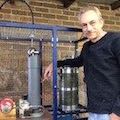
Pix -- here is the emission source and the whole thing mounted on my big tank. I floated the focus/emitter power supplies on the little table so I can apply serious HV to the whole mess to get a powerful beam that enters the tank at "ground" potential. It works surprisingly well for an empirical design (eg the "looks right method"). The lenses are machined to fit inside the pyrex segments except for a ring in the middle which is where the apezion goes to seal them. I plan to rebuild this to use closer lens element spacing which should work better. This nets about 20ma to a target in the tank at whatever HV I'm willing to put on it. The ring mount into the tank itself is the final accelerating electrode, at ground potential. I adjust the focus and emission pots with a long fiberglass stick with a screwdriver bit mounted on the end. To work, this needs to run at the E-5 mbar level or below, but if you let in some noble gas you can run it for awhile at a slightly higher pressure and see the beam. I use a couple of gel cells to run the filament and focus power supplies, the latter of which is a CCFL inverter and some diodes that uses a 3 terminal voltage regulator on the input to adjust the voltage.
I have used 6v 2A quartz halogen bulbs (from lawn fixtures) with very good success for electron emitters. BillF found me some Y2O3 to coat them with, and it helps greatly, while being relatively resistant to occasional air exposure. A low voltage/high current filament is best, and the one from a magnetron ought to be very good too, but is sort of 90 deg turned the wrong way..Low volts is good as there won't be as much difference in potential across the filament to foul up efforts at focus. I built an E-gun based on this to fool around and be a heat source that used .7" ID, 1.1" OD pieces of bronze pipe between pieces of 1" pyrex for the lensing and accelerators, and it works fairly well. With the small 6v bulbs and Y2O3 I run about 2.1-2.5 volts and get about 30 ma emission (depends on the voltage gradient to suck the space charge off the virtual cathode). Without the coating, it takes about a volt more, and they don't last nearly as long. I use a diamond wheel in a dremel tool mounted on the toolpost of my lathe to cut the tops off the bulbs and leave a smooth surface to seal onto the vacuum system with apezion wax. Hysol or JB weld would probably work too, but you wind up replacing these once in awhile...I mount mine to a fat piece of copper rod I machined out on my lathe to be a Pierce diode, and I put a heatsink on the outside of this to keep it cool so the apezion doesn't melt in use.
Another promising candidate is tungsten-rhenium alloy wire from type C thermocouples, which is supposed to be a lot more resistant to oxygen. It is certainly more ductile than pure tungsten.
Haven't tried this myself so far, but I get the stuff from Nanmac, and it's available in small gauges (but the price will make you wince). It has a lot more resistance than pure tungsten, so you can use a fatter size for the same length.
Triple carbonate filaments as used in normal vacuum tubes will not take exposure to air; once activated they have pure Ba, Sr, and Ca which is what does the emission -- it's the same stufff used as a getter! I have successfully rejuvenated them once or twice, but that's it, and each time they emit less than the time before. The older ones (thicker coatings) are the ones that can go 3 times. You could reuse a CRT gun but you'd have to replace the emitter with something more robust -- I plan to try this myself, as they are better precision than things I can easily make here (but small aperture and low current).
For low volts and high current, the best source is probably going to be a switching supply from an electronics surplus house. You can also make one by chiseling off and rewinding the secondary from a microwave oven transformer -- we have done that here a few times. Take out the extra iron between the windings, and if you want it to run cool, add about 20 turns in series with the primary, as these normally run deep in core saturation and get hot. We use them to heat evaporation tubs in the few volt hundred amp region with great success. But the size of the filter caps you would need for DC with low ripple at high current is prohibitive. So the switcher is the way to go, and not all that expensive. IIRC I got a 3.3v 150A supply from Marlin Jones for under $100.
Seltzman found out you can't push enough Fluoinert through a tiny tube to get much cooling, even with a positive displacement pump. If you need fat tubing you could probably use mineral oil as a coolant just fine. I get mine at McMaster-Carr, it's very pure and a great insulator. I am using it here to replace the PCB oil in some old X ray supplies I am rebuilding with success.
Try to keep away from plastics, They may not all (or always) be as bad as stated above, but they are easy to heat to the point of trouble in a vacuum, even the rather expensive polyimide and teflon. Even pyrex glass can be a problem as it will shatter if suddenly heated by a stray beam -- a real mess to clean up (and if you're running a turbo, can wreck it). I use alumina. For protecting my main windows, I use another pyrex disc, again from McMaster. This way when it gets coated, I can just dunk it in the pickling tank from my electroplating setup. I hold them up to the original port with some tiny CuBe clips around the edge so they are easy to R&R. This avoids having to put acid on the nice glass to metal seal of a main window or door. Mica also works pretty well for this.
Pix -- here is the emission source and the whole thing mounted on my big tank. I floated the focus/emitter power supplies on the little table so I can apply serious HV to the whole mess to get a powerful beam that enters the tank at "ground" potential. It works surprisingly well for an empirical design (eg the "looks right method"). The lenses are machined to fit inside the pyrex segments except for a ring in the middle which is where the apezion goes to seal them. I plan to rebuild this to use closer lens element spacing which should work better. This nets about 20ma to a target in the tank at whatever HV I'm willing to put on it. The ring mount into the tank itself is the final accelerating electrode, at ground potential. I adjust the focus and emission pots with a long fiberglass stick with a screwdriver bit mounted on the end. To work, this needs to run at the E-5 mbar level or below, but if you let in some noble gas you can run it for awhile at a slightly higher pressure and see the beam. I use a couple of gel cells to run the filament and focus power supplies, the latter of which is a CCFL inverter and some diodes that uses a 3 terminal voltage regulator on the input to adjust the voltage.
- Attachments
-
-
Why guess when you can know? Measure!