I've been working on a new fusor for the last 10 days. I intended to spare the forum my day to day progress this time and only report when I have my project done. However, I encountered something yesterday I haven't seen before, and I thought I would share.
I had come to the conclusion that my fusors do better with an uninsulated stem. I have done the alumina thing and found it to be an expensive waste because I often got lots of sparks that took forever to get rid of unless I let a bare stem clean quickly. I haven't had a problem with this until yesterday.
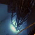
My feed through is homemade from a relatively large, two-post standoff insulator silver soldered to a 6 inch CF flange. I put a slender piece of all- thread through one of the posts for my stem. To center my grid I put a bend in the stem.
As you can see from my picture, plasma forms preferentially within my feed through and only a small amount forms in the grid. I suspect the stem, with its bend is forming a grid.
I plan to try two things to solve the problem. I have changed the bend to a more gradual one and added alumina beads along its length. I will report the results soon.
There have been some other interesting developments, but i will report out on that later.
Jim K
Grid stem ...plasma where it shouldn't be
-
Jim Kovalchick
- Posts: 717
- Joined: Wed Apr 13, 2011 8:00 pm
- Real name:
Grid stem ...plasma where it shouldn't be
- Attachments
-
-
Frank Sanns
- Site Admin
- Posts: 2124
- Joined: Fri Jun 14, 2002 2:26 pm
- Real name: Frank Sanns
Re: Grid stem ...plasma where it shouldn't be
It is difficult to see from the picture if your insulator continues all of the way into the chamber or not. Does it end where the all thread enters the vacuum or does it end where it enters the main chamber? Most of us with feedthroughs have the later. This provides an insulator within the feedthrough even though it is a bare shaft.
Distance is everything inside a Fusor. When a HV metal element comes close to a grounded surface the inverse square law shows up quickly. A bare metal rod going through a metal cylinder into the main chamber is going to have problems because of the shorter electrical path due to higher field strength.
You can get away with a non insulated stalk once in the chamber but most likely not when passing through a metal pipe on the way to the main chamber.
Achiever's madness; when enough is still not enough. ---FS
We have to stop looking at the world through our physical eyes. The universe is NOT what we see. It is the quantum world that is real. The rest is just an electron illusion. ---FS
We have to stop looking at the world through our physical eyes. The universe is NOT what we see. It is the quantum world that is real. The rest is just an electron illusion. ---FS
-
Jim Kovalchick
- Posts: 717
- Joined: Wed Apr 13, 2011 8:00 pm
- Real name:
Re: Grid stem ...plasma where it shouldn't be
Frank,
The insulator comes part way into the chamber but not the whole way into the cross leg. I will say though that I did the same thing with my 2.75 CF cross and did not see this problem.
The insulator comes part way into the chamber but not the whole way into the cross leg. I will say though that I did the same thing with my 2.75 CF cross and did not see this problem.
-
Jim Kovalchick
- Posts: 717
- Joined: Wed Apr 13, 2011 8:00 pm
- Real name:
Re: Grid stem ...plasma where it shouldn't be
Frank,
I understand your questions, but i don't understand why the plasma is forming within the insulated feed through pipe.
I understand your questions, but i don't understand why the plasma is forming within the insulated feed through pipe.
-
Richard Hull

- Moderator
- Posts: 15039
- Joined: Fri Jun 15, 2001 9:44 am
- Real name: Richard Hull
Re: Grid stem ...plasma where it shouldn't be
Is a puzzlement. (the king and I)
Jim, I dare not pontificate from afar on this matter. Could you give a cross-sectional diagram in paint or such that accurately (not to the .1-inch, of course), depicts what you have. Mainly where the bend begins related to the grounded metal and such. also include the relative or guessed at clearances.
We will have this to discuss at HEAS for sure, whether you find a fix or not. I have seen these two entrant insulators which should do fine for many here that go begging for being less than ideal.
I attach my thoughts in diagrammatic form.
Richard Hull
- Attachments
-
Progress may have been a good thing once, but it just went on too long. - Yogi Berra
Fusion is the energy of the future....and it always will be
The more complex the idea put forward by the poor amateur, the more likely it will never see embodiment
Fusion is the energy of the future....and it always will be
The more complex the idea put forward by the poor amateur, the more likely it will never see embodiment
-
Jim Kovalchick
- Posts: 717
- Joined: Wed Apr 13, 2011 8:00 pm
- Real name:
Re: Grid stem ...plasma where it shouldn't be
It is bizarre because the plasma is forming at a point on the stem that is further from bare, grounded metal than the grid. I tried again with overlapping beads on the stem, but plasma emerges from joints during a 10 kV test and along a portion of the stem not covered with the beads. The plasma is "fighting" the grid plasma. A full star in the grid will pulse on and off alternately with pulses of plasma along the stem.
I may have time to take some better pictures later
I may have time to take some better pictures later
-
Richard Hull
- Moderator
- Posts: 15039
- Joined: Fri Jun 15, 2001 9:44 am
- Real name: Richard Hull
Re: Grid stem ...plasma where it shouldn't be
The bend alters the field control. Nothing should be much off perfect center throughout the insulator to the grid.
Richard Hull
Richard Hull
Progress may have been a good thing once, but it just went on too long. - Yogi Berra
Fusion is the energy of the future....and it always will be
The more complex the idea put forward by the poor amateur, the more likely it will never see embodiment
Fusion is the energy of the future....and it always will be
The more complex the idea put forward by the poor amateur, the more likely it will never see embodiment
-
Jim Kovalchick
- Posts: 717
- Joined: Wed Apr 13, 2011 8:00 pm
- Real name:
Re: Grid stem ...plasma where it shouldn't be
I have used this configuration on a bigger chamber without this issue. On my latest run, the plasma formed at the inside base of the feed through. The plasma arcs were buzzing. Yuck
- Attachments
-
-
-
Dennis P Brown

- Posts: 3190
- Joined: Sun May 20, 2012 10:46 am
- Real name: Dennis Brown
Re: Grid stem ...plasma where it shouldn't be
In the second photo, I assume the alumina tubes are not sealed to the base where the wire connects to the electrode so the plasma is free to short to the local ground; can't tell from the photo if that is the case.
-
Jim Kovalchick
- Posts: 717
- Joined: Wed Apr 13, 2011 8:00 pm
- Real name:
Re: Grid stem ...plasma where it shouldn't be
Dennis,
The alumina is not sealed at the base. Does anyone do that? I'm not aware of any ground near this until you leave the tube of the feed through. It appears that plasma is forming there and causing current to flow. I have not heard of this problem in anyone's feed through before.
Jim K
The alumina is not sealed at the base. Does anyone do that? I'm not aware of any ground near this until you leave the tube of the feed through. It appears that plasma is forming there and causing current to flow. I have not heard of this problem in anyone's feed through before.
Jim K
-
Richard Hull
- Moderator
- Posts: 15039
- Joined: Fri Jun 15, 2001 9:44 am
- Real name: Richard Hull
Re: Grid stem ...plasma where it shouldn't be
The thing looks like it should work well. I am out of suggestions beyond some sort of micro crack or conductive path up the stem. The conduction and gas ionization are up in the insulator where the sharp shoulder of the conflat is, I assume?
Richard Hull
Richard Hull
Progress may have been a good thing once, but it just went on too long. - Yogi Berra
Fusion is the energy of the future....and it always will be
The more complex the idea put forward by the poor amateur, the more likely it will never see embodiment
Fusion is the energy of the future....and it always will be
The more complex the idea put forward by the poor amateur, the more likely it will never see embodiment
-
Jim Kovalchick
- Posts: 717
- Joined: Wed Apr 13, 2011 8:00 pm
- Real name:
Re: Grid stem ...plasma where it shouldn't be
I wonder if i need to bake out or otherwise dry out my feed through. I think before the next time I try it, I will let the vacuum system run a much longer time period.
This feed through is a big chunk of material. Maybe it absorbs water and sir more than my normal feed through.
This feed through is a big chunk of material. Maybe it absorbs water and sir more than my normal feed through.
-
Dennis P Brown
- Posts: 3190
- Joined: Sun May 20, 2012 10:46 am
- Real name: Dennis Brown
Re: Grid stem ...plasma where it shouldn't be
Extra pumping and especially a bake out are very good ways to test that issue. I'd be extremely surprised if that didn't mostly solve the issue relative to arcing.
Most commercial feed-thru's are continious tubes - from the outside to well into the chamber.
I've built a few home-made ones as well and yes, leakage from that location (ceramic tube sheath over the metal electrode) occurs at the base where it meets the glass interface plate and yet still bleeds away power from the fusor cathode.
I will (hopefully) soon be finishing my new one. I will address that issue via a ceramic tube going all the way through the conflat and well into the chamber without a break. I will seal the ceramic tube to the metal electrode/rod via molten glass. Then an o-ring will seal the ceramic tube into the conflat coupling for the chamber. In this way I will mimic a commercial HV feed-thru.
-
Richard Hull
- Moderator
- Posts: 15039
- Joined: Fri Jun 15, 2001 9:44 am
- Real name: Richard Hull
Re: Grid stem ...plasma where it shouldn't be
Is the part of the insulator that protrudes into the vacuum glazed or is it matt, "as fired"? If matt, then moisture may be the issue. The antenna bulk head insulator I use is glossy, slick glazed like glass on the vacuum entrant part of the insulator.
Richard Hull
Richard Hull
Progress may have been a good thing once, but it just went on too long. - Yogi Berra
Fusion is the energy of the future....and it always will be
The more complex the idea put forward by the poor amateur, the more likely it will never see embodiment
Fusion is the energy of the future....and it always will be
The more complex the idea put forward by the poor amateur, the more likely it will never see embodiment
-
Jim Kovalchick
- Posts: 717
- Joined: Wed Apr 13, 2011 8:00 pm
- Real name:
Re: Grid stem ...plasma where it shouldn't be
All exposed interior parts of the insulator are unglazed.
I did a run today with zero alumina and only after a long pump down. I had plasma forming in the insulator but none of the plasma arcing and snapping i get when I use alumina.
I saw signs that I was driving stuff out out my insulator because if sat at a single voltage the current would slowly drop until I bumped up voltage. If I raised current there was sometimes a rise in pressure.
I never did get to the point that I could flash plasma only in the grid.
I am investigating other possibilities. I wonder if i have a vacuum leak on my feed through.
- Attachments
-
-
Richard Hull
- Moderator
- Posts: 15039
- Joined: Fri Jun 15, 2001 9:44 am
- Real name: Richard Hull
Re: Grid stem ...plasma where it shouldn't be
That is a good thought about the possible leak. I have no doubt you will solve the issue.
Richard Hull
Richard Hull
Progress may have been a good thing once, but it just went on too long. - Yogi Berra
Fusion is the energy of the future....and it always will be
The more complex the idea put forward by the poor amateur, the more likely it will never see embodiment
Fusion is the energy of the future....and it always will be
The more complex the idea put forward by the poor amateur, the more likely it will never see embodiment
-
Dennis P Brown
- Posts: 3190
- Joined: Sun May 20, 2012 10:46 am
- Real name: Dennis Brown
Re: Grid stem ...plasma where it shouldn't be
A lot of heat diffuses down the metal rod but that commercial 'feed thru', I'd think should be able to handle that. Have you tried the alcohol test on that part when it is in high vac?
-
Jim Kovalchick
- Posts: 717
- Joined: Wed Apr 13, 2011 8:00 pm
- Real name:
Re: Grid stem ...plasma where it shouldn't be
Dennis,
I did an alcohol test today. No leaks.
I did an alcohol test today. No leaks.
-
Dennis P Brown
- Posts: 3190
- Joined: Sun May 20, 2012 10:46 am
- Real name: Dennis Brown
Re: Grid stem ...plasma where it shouldn't be
Excellent and good news on no leaks; then likely just out gassing and stuff feeding the plasma.
Have you tried cleaning the alumina tube? This can be done with a dilute dish washing solution. Followed by thoroough hot water rinse. Next alcohol cleaning. Then waer gloves to hold it and either use a can of 'dry air' to blow off water droplets (if available) or use a clean, lint free cloth to dry. Finally, again, only handle with clean gloves and install. Pull a high vac and then try a plasma burn off.
Aside - the alumina has no sharp edges - i.e. all edges have been rounded.
-
Jim Kovalchick
- Posts: 717
- Joined: Wed Apr 13, 2011 8:00 pm
- Real name:
Re: Grid stem ...plasma where it shouldn't be
Plasma is now where it should be. I went back to my old 30 kV feed through and moved my grid back as close to the feed through as I could.
I'm using a 6 inch cross, but the business is mostly happening in one end of it. I have two titanium sheets surrounding the grid. The enclosed area drives the plasma pressure relatively high. The star is not very symmetrical, but it still makes neutrons. I'm getting thousands of cpm on my CHM 11 tube at 38 kV and 8 mA, but I'm not confident in the numbers because I'm still getting arcs as the parts get used to the higher voltages.
I note that this viewport doesn't give a lot of xray sparkle in my photos. It has an extra disc of borosilicate glass that is probably helping with xrays. I'll still end up shielding it when I consider this fusor done.
- Attachments
-
-
-
Richard Hull
- Moderator
- Posts: 15039
- Joined: Fri Jun 15, 2001 9:44 am
- Real name: Richard Hull
Re: Grid stem ...plasma where it shouldn't be
Very interesting image. I am glad you got the plasma to be in the right place. See you in a couple of weeks, Jim.
Richard Hull
Richard Hull
Progress may have been a good thing once, but it just went on too long. - Yogi Berra
Fusion is the energy of the future....and it always will be
The more complex the idea put forward by the poor amateur, the more likely it will never see embodiment
Fusion is the energy of the future....and it always will be
The more complex the idea put forward by the poor amateur, the more likely it will never see embodiment
-
Jim Kovalchick
- Posts: 717
- Joined: Wed Apr 13, 2011 8:00 pm
- Real name:
Re: Grid stem ...plasma where it shouldn't be
I decided to remove the titanium sheets from my latest fusor. I found that pressure and therefore current runs up too much making the fusor extremely difficult to control. During one run I delicately changed gas flow in with successive adjustments to keep current in an operating range i consider safe for my power supply and grid, and after several minutes I found that I had nearly shutoff gas going in. Outgassing, apparently from the titanium, was sufficient to maintain the plasma current and then some. I am guessing I must have loaded up the titanium from earlier runs. I dont believe this was moisture or nitrogen because the plasma ignition pressure remained much higher than that seen during my air runs.
Removal of the titanium sheets removed this difficult operating characteristic. I did trade one problem for another. Because removal of the sheets exposed the openings of the chamber cross orthogonal to my grid axis, there is a predominant beam. I need to tweak the grid orientation to get more symmetry.
I have attached a couple pictures. The image with only the horizontal beam is higher voltage and lower pressure.
It would seem this fusioneer's work is not yet done.
- Attachments
-
-
-
Richard Hull
- Moderator
- Posts: 15039
- Joined: Fri Jun 15, 2001 9:44 am
- Real name: Richard Hull
Re: Grid stem ...plasma where it shouldn't be
This is probably cross related. spheres and long cylinders tend no to see this issue. I have no doubt, you will work it out.
Richard Hull
Richard Hull
Progress may have been a good thing once, but it just went on too long. - Yogi Berra
Fusion is the energy of the future....and it always will be
The more complex the idea put forward by the poor amateur, the more likely it will never see embodiment
Fusion is the energy of the future....and it always will be
The more complex the idea put forward by the poor amateur, the more likely it will never see embodiment