Mark3 operation 3e-4 torr / quad ion source @ -40kV, 1mA-9mA

For posts specifically relating to fusor design, construction, and operation.
Andrew Seltzman
Posts: 810
Joined: Sun Feb 01, 2004 8:02 pm
Real name: Andrew Seltzman
Contact:

Re: Mark3 operation 3e-4 torr / quad ion source @ -40kV, 1mA

Post by Andrew Seltzman »

The fusor has been upgraded to help combat the outgassing/permeation problem by replacing the delrin insulator with a PEEK/stainless insulator and using copper o-rings. Fastener hardware was chosen to be silver plated 12pt bolts additionally coated with moly based anti-seize compound.

Currently the modification changes the system from 16x to 11x 2.75" CF viton o-rings, 1x to 0x 8" CF viton o-rings, 45.6 cm^2 delrin surface area(8e-7 TL/s/(cm^2)) to 7.6 cm^2 PEEK surface area(2.9e-7 TL/s/(cm^2))

Parts for upgrade
SAM_4479a.jpg
Conflat cube
SAM_4480a.jpg
Replacing viton with copper o-rings
SAM_4481a.jpg
0.25" high, 1.5" ID PEEK insulator and 1.5" high stainless coupler to replace 1.5" high, 1.5" ID Delrin insulator, reduces outgassing rate from 3.6e-05 TL/s to 2.2e-06 TL/s
SAM_4485a.jpg
Anti-seize coated stainless studs, used with silver plated nuts
SAM_4486a.jpg
Re-fitted cube
SAM_4488a.jpg
Core hemisphere
SAM_4489a.jpg
Deposition on ceramic fabric o-ring shield
SAM_4491a.jpg
Condition of grid insulator
SAM_4495a.jpg
Pre-annealed(for easier tightening) copper o-ring
SAM_4497a.jpg
Port alignment jig, to ensure alignment of opposing conflat ports(optical and ion source)
SAM_4498a.jpg
New stainless/PEEK insulating break
SAM_4499a.jpg
Core bolted together
SAM_4500a.jpg
Additionally a lead glass disk has been added to the pyrex viewport for x-ray shielding, previously there was a lead glass rectangle that had some standoff distance reducing the field of view for taking pictures, the new disk fits into the conflat ring giving the disk more protection and making it easier to take pictures.
SAM_4466a.jpg
SAM_4467a.jpg
Andrew Seltzman
www.rtftechnologies.org
User avatar
Richard Hull
Moderator
Posts: 15023
Joined: Fri Jun 15, 2001 9:44 am
Real name: Richard Hull

Re: Mark3 operation 3e-4 torr / quad ion source @ -40kV, 1mA

Post by Richard Hull »

Again, fabulous, plus ultra rig. It is going to work brilliantly.

Richard Hull
Progress may have been a good thing once, but it just went on too long. - Yogi Berra
Fusion is the energy of the future....and it always will be
The more complex the idea put forward by the poor amateur, the more likely it will never see embodiment
Andrew Seltzman
Posts: 810
Joined: Sun Feb 01, 2004 8:02 pm
Real name: Andrew Seltzman
Contact:

Re: Mark3 operation 3e-4 torr / quad ion source @ -40kV, 1mA

Post by Andrew Seltzman »

With the new modifications the fusor achieves a base pressure of 8.9e-5 torr after 10h of pumping (compared to 1.9e-4 before), so the gas source was not the delrin, though the system feals like it runs a lot cleaner. It will pump down from 70mTorr to the low E-4 torr range in about 10min as compared to 1-2 hours before, and will sustain operation in the low E-4 range without the pressure climbing up to the mTorr range.

Vacuum pumpdown with new system
pumpdown1-10-18-2015-copper-orings-peek-insulator.jpg
pumpdown2-run-10-18-2015.jpg
Vacuum rise after valve-off with new system
10h-ultimate-vacuum-rise.jpg
10h-ultimate-vacuum-rise2.jpg
Star mode operation at 1E-4 Torr
10h-ultimate-vacuum-star-mode.jpg
SAM_4505aa.jpg
Andrew Seltzman
www.rtftechnologies.org
User avatar
Jim Kovalchick
Posts: 717
Joined: Wed Apr 13, 2011 8:00 pm
Real name:

Re: Mark3 operation 3e-4 torr / quad ion source @ -40kV, 1mA

Post by Jim Kovalchick »

Andrew,
I know its too late now, but did you try conditioning your delrin prior to use?

A couple years ago my son did some work that required him to use silicon rubber inside a vacuum chamber. Predictably, the stuff was a massive outgas source. He ended up sonicating the rubber in pure isopropanol for hours followed by a slow bake out in the kitchen oven. The results were amazing and outgassing was significantly reduced. I have no idea if that would work for delrin or any other outgas sponge material, but it's a technique to keep in the toolbox if you ever "have" to use a material that is normally a problem.
Andrew Seltzman
Posts: 810
Joined: Sun Feb 01, 2004 8:02 pm
Real name: Andrew Seltzman
Contact:

Re: Mark3 operation 3e-4 torr / quad ion source @ -40kV, 1mA

Post by Andrew Seltzman »

Yes I did, the delrin was baked in a vacuum oven at over 100C for 24h.
Andrew Seltzman
www.rtftechnologies.org
Bern Bareis
Posts: 21
Joined: Sun Mar 29, 2015 10:40 pm
Real name: Bern Bareis

Re: Mark3 operation 3e-4 torr / quad ion source @ -40kV, 1mA

Post by Bern Bareis »

Andrew,

If the images above are representative of your system in the configuration that you were testing, you may want to consider putting bolts in all 2-3/4" CF mounting holes and tightening to the proper torque. It has been my experience that not doing so results in leaks. For the 2-3/4" CF bolts, the industry applied torque is typically 12 ft-lbs and for the 8" CF bolts, the industry applied torque is typically 15 ft-lbs. The tightening method applied is generally a crisscross pattern to finger tight or snug with all bolts in place and then a round-robin pattern going around at least 3 times tightening more on each successive time around, until the proper torque is reached.

Nice work on your upgrades.
Andrew Seltzman
Posts: 810
Joined: Sun Feb 01, 2004 8:02 pm
Real name: Andrew Seltzman
Contact:

Re: Mark3 operation 3e-4 torr / quad ion source @ -40kV, 1mA

Post by Andrew Seltzman »

Bern,

All 2.75" cf flanges with copper o-rings have all bolts used. there are some 2.75 CF ports that use viton o-rings that don't use all the bolts(like the ion injectors and viewports). The 8" CF flange uses a pre-annealed copper o-ring(for easier tightening) and all but 4 bolts. Those bolt holes were needed to be free for the insulated mounting bolts to hold the core to the frame (still using only one ground return path through the grounding wire to avoid ground loops).
Andrew Seltzman
www.rtftechnologies.org
Bern Bareis
Posts: 21
Joined: Sun Mar 29, 2015 10:40 pm
Real name: Bern Bareis

Re: Mark3 operation 3e-4 torr / quad ion source @ -40kV, 1mA

Post by Bern Bareis »

Hi Andrew,

Noting from the images above it appears that the ion injectors are attached with metal bolts (eliminating electrical isolation), is there a compelling reason not to use copper o-rings on the 2-3/4" CFs for the ion injectors?

If you don't require a lower vacuum pressure, then perhaps it is not an issue at this point. However, with copper o-rings for almost all connections I would expect that you would be able to get close to an order of magnitude lower vacuum pressure after 10 minutes of turbomolecular pump operation (i.e. E-5 Torr range based on your turbomolecular pump specifications and vacuum chamber size, assuming no significant leaks).
Andrew Seltzman
Posts: 810
Joined: Sun Feb 01, 2004 8:02 pm
Real name: Andrew Seltzman
Contact:

Re: Mark3 operation 3e-4 torr / quad ion source @ -40kV, 1mA

Post by Andrew Seltzman »

Bern,

Unfortunately all copper o-rings are not an option at this time. There are 5 viewports, 3 pyrex, 2 ZnSe that require viton o-rings, as well as 2 o-rings for the insulating spacer. There is also an NW40 for the vacuum gauge, and an NW16 for the valve. There are some places that sell aluminum NW o-rings, how well do these work?

I do plan to replace the ion injector viton o-rings with copper o-rings, but have not done to it yet, there are few things I want to do first.

There is a trapped volume problem with the mounting standoff holding the injector to the CF flange. The standoff and screw are both vented, but when the standoff is screwed into the flange, the thread bottoms out, potentially sealing off the vent, I have built some spacer washers(also vented) to fix this problem.
SAM_4472a.jpg
SAM_4471a.jpg
SAM_4475a.jpg
Secondly, the injectors have a movable central cathode pole to adjust beam focus, currently they are set for a cylindrical beam, but I want to change it to focus at about 3" from the injector so they are focused at the center of the grid. I have a fifth identical injector on a test bed that I can try this out with.

Thirdly, I would like to have some custom alumina insulator standoffs machined for the anode ring support, currently they have steel clips holding the alumina rods in place, but they can slide, so I'd like to have one with a step machined.
Andrew Seltzman
www.rtftechnologies.org
Bern Bareis
Posts: 21
Joined: Sun Mar 29, 2015 10:40 pm
Real name: Bern Bareis

Re: Mark3 operation 3e-4 torr / quad ion source @ -40kV, 1mA

Post by Bern Bareis »

Hi Andrew,

According to the specifications for the aluminum metal seals "aluminum o-rings" for replacement of Viton o-rings, the leak rate is expected to be less than 1E-11 standard cc/sec. That leak rate is also likely measured using the chain clamps that go with them. Obviously, there are tradeoffs in what you want to accomplish for your experimental setup versus the type of gasket seal or o-ring that you can apply. If lower vacuum pressure is of interest to you, then replacing more Viton o-rings with metal gasket seals will help. You don't necessarily need to replace all of the Viton o-rings, but if you can get the number down to 1 or 2 from in your vacuum chamber through to the turbomolecular pump, then I would think you would get an order of magnitude or more reduction in the vacuum pressure in the first ten minutes of operating the turbomolecular pump, assuming that there is not any excessive constriction in the tubing connecting your turbomolecular pump to the vacuum chamber.
Andrew Seltzman
Posts: 810
Joined: Sun Feb 01, 2004 8:02 pm
Real name: Andrew Seltzman
Contact:

Re: Mark3 operation 3e-4 torr / quad ion source @ -40kV, 1mA

Post by Andrew Seltzman »

Some new upgrades:

Deuterium supply and control:
Got a better quality lecture bottle regulator on ebay
SAM_4520a.jpg
Testing regulator with argon
SAM_4523a.jpg
A piezoelectric valve is being outfitted to control pressure in the fusor.
SAM_4431a.jpg
Converting the valve from swagelok tube to VCR inlet and outlet ports
SAM_4430a.jpg
Deuterium/dry air admit(for venting the core to atmosphere) manifold to attach to the back of the conflat cube, used swagelok SS-4H bellows sealed valves w/ 1E-9 TL/s leak rate
SAM_4513a.jpg
Bakeout system, to drive water/contaminants off the chamber walls without running plasma(reduces ware on grid / metal deposition from using ion bombardment to heat the chamber walls)

20W stick on heater
SAM_4519a.jpg
8x heaters(160w total) attached to the core
SAM_4518a.jpg
Heaters connected to fusor 24v power supply
SAM_4516a.jpg
Bake out of core after up to dry air to install deuterium manifold, bakeout had to be stopped to prevent damage to the magnets shielding the viewports from ion beam damage(80c max), core reached 90-100C, though cooler out on the nipples
bakeout-130c-annotated.jpg
Andrew Seltzman
www.rtftechnologies.org
Andrew Seltzman
Posts: 810
Joined: Sun Feb 01, 2004 8:02 pm
Real name: Andrew Seltzman
Contact:

Re: Mark3 operation 3e-4 torr / quad ion source @ -40kV, 1mA

Post by Andrew Seltzman »

Latest test runs:

Pump down time after the bakeout has decreased to 10min to get from 500mTorr to 3e-4 torr

A second lead glass shield on the topside viewport has been added allowing pictures of the upper segment of the grid

Operation at 40kV, 2.2e-4 Torr
SAM_4528.JPG
Interestingly enough it seems like only the bottom viewport fluoresces under ion bombardment(residual ones not deflected by the shield magnet), not the top one. Also there is in interesting fluorescing pattern on the top of the boron nitride insulator
SAM_4528b.JPG
It looks like secondary electrons from the grid are hitting the top of the insulator causing the fluorescence, however there is a dark area between the grid rings, apparently where there are no electrons hitting. The incoming ions hitting the outer surface of the grid are generating secondary electrons streaming off the grid, however the electric field directs them radially outward causing the dark area between rings.
Andrew Seltzman
www.rtftechnologies.org
Andrew Seltzman
Posts: 810
Joined: Sun Feb 01, 2004 8:02 pm
Real name: Andrew Seltzman
Contact:

Re: Mark3 operation 3e-4 torr / quad ion source @ -40kV, 1mA

Post by Andrew Seltzman »

Operation in the 9e-5 to 1e-4 torr vacuum range
SAM_4534c.jpg
Video of the plasma during voltage ramp up
https://www.youtube.com/watch?v=4pOdWpW ... e=youtu.be

You can see the structure of the ion beam coming from the opposing sources, compared to a picture of the ion beam from the injector in a test bed with no grid potential, particularly on the lower left beam
SAM_3244a.jpg
The cylindrical beam is being focused by the grid potential into a conical beam. I think it might be useful to put some focusing directly on the injector to get a tighter beam at the focal point.
Andrew Seltzman
www.rtftechnologies.org
Andrew Seltzman
Posts: 810
Joined: Sun Feb 01, 2004 8:02 pm
Real name: Andrew Seltzman
Contact:

Re: Mark3 operation 3e-4 torr / quad ion source @ -40kV, 1mA

Post by Andrew Seltzman »

First fusion test runs with the new system

System setup with piezo control valve and deuterium tank(an older one with about 90psi left in it) and regulator)
SAM_4536.JPG
Deuterium tank and regulator
SAM_4538.JPG
Piezo control valve, takes a 0-100V signal, accurately admits gas to the fusor allowing operation in the 3e-4 to >10mTorr range
SAM_4539.JPG
Valve control circuit, 90v boost converter and potentiometer to control valve voltage
SAM_4537.JPG
Gas inlet manifold on back of cube
SAM_4553.JPG
Pressure during fusion test run
fusion-run.jpg
Star view, bottom, ~6mTorr
SAM_4542.JPG
Star view top, ~6mTorr
SAM_4546.JPG
Videos of test run
https://youtu.be/sZnh9uPCKvU
https://youtu.be/3hJ6Pn14SL4
https://youtu.be/dqJbiwHoiNk


Some counts detected on a BF3 type neutron detector, no exact calculation of neutron flux yet
Operation in the 3e-4 torr to 8mTorr range
40kV on the grid, ~5-8mA current
Andrew Seltzman
www.rtftechnologies.org
User avatar
Steven Sesselmann
Posts: 2128
Joined: Wed Aug 10, 2005 9:50 pm
Real name: Steven Sesselmann
Location: Sydney - Australia
Contact:

Re: Mark3 operation 3e-4 torr / quad ion source @ -40kV, 1mA

Post by Steven Sesselmann »

Andrew,

Beautiful engineering as always on your projects.

Did you have the ion sources running during this run?

I am really interested in your ion sources, is there a post describing these in more detail?

Steven
http://www.gammaspectacular.com - Gamma Spectrometry Systems
https://www.researchgate.net/profile/Steven_Sesselmann - Various papers and patents on RG
Andrew Seltzman
Posts: 810
Joined: Sun Feb 01, 2004 8:02 pm
Real name: Andrew Seltzman
Contact:

Re: Mark3 operation 3e-4 torr / quad ion source @ -40kV, 1mA

Post by Andrew Seltzman »

Yes, all 4 ion sources were on. you can see the distinct difference in a gunned fusor, in that the star mode only has 4 rays(for an 3 ring grid with 8 openings), with no visible rays coming out of the segments of the grid where there are no ion sources feeding in ions.

The ion source designs are
viewtopic.php?f=12&t=5011
and
http://www.rtftechnologies.org/physics/ ... source.htm
Andrew Seltzman
www.rtftechnologies.org
User avatar
Steven Sesselmann
Posts: 2128
Joined: Wed Aug 10, 2005 9:50 pm
Real name: Steven Sesselmann
Location: Sydney - Australia
Contact:

Re: Mark3 operation 3e-4 torr / quad ion source @ -40kV, 1mA

Post by Steven Sesselmann »

Andrew,

Thanks for the links, it seems my memory is not so good, I was active in your ion source thread back in 2009, phew time flies when one is doing fusion...

If your ion source can operate with negative bias, I think it would be a worth while experiment to do a fusion run with a) Positive bias and b) Negative bias, if I am not mistaken you should see more fusion with a negatively biased ion source. As you are only running a few kV the central grid will still be able to extract the ions.

Read my recent post to understand my reasoning (viewtopic.php?f=50&t=10443)

Steven
http://www.gammaspectacular.com - Gamma Spectrometry Systems
https://www.researchgate.net/profile/Steven_Sesselmann - Various papers and patents on RG
Andrew Seltzman
Posts: 810
Joined: Sun Feb 01, 2004 8:02 pm
Real name: Andrew Seltzman
Contact:

Re: Mark3 operation 3e-4 torr / quad ion source @ -40kV, 1mA

Post by Andrew Seltzman »

Neutron output is estimated to be in the 25k-30k per sec range based on an ~500sec run at about 8mTorr, 40kv, 8ma, 8.9cm radius from BTI to center, both a BTI bubble dosimeter(pretty old, won't recompress, 8 bubbles present before run started, ~29 after run). Flux estimate from BTI matches estimate from BF3 neutron detector
SAM_4559.JPG
the neutron rate drops off pretty rapidly as things heat up and start to outgas, requiring reduction in D2 flow and thus reducing plasma purity. I might need to redesign the grid to remove the BN ceramic which I suspect may be the main source of temperature driving outgassing.
Andrew Seltzman
www.rtftechnologies.org
Andrew Seltzman
Posts: 810
Joined: Sun Feb 01, 2004 8:02 pm
Real name: Andrew Seltzman
Contact:

Re: Mark3 operation 3e-4 torr / quad ion source @ -40kV, 1mA

Post by Andrew Seltzman »

I've been getting my bubble dosimeter to re-compress by inserting a pencil eraser in between the screw on tap and the rubber membrane(still looking o buy a new one). This one was purchased in 2009 and is still working with some effort to get it to re-compress. The only thing that i notice is the bubbles are smaller then when it was new.


Best neutron numbers to date 2.1E5 n/s at 8mTorr, 40kV, 8.9ma, 4 ion injectors at 700v anode voltage
24 bubbles over a 100sec run
SAM_4568a.jpg
Calculations
http://www.gammaspectacular.com/fusion_calculator.html
fusion11-21-2015.jpg
Something is still heading up and outgassing which requires the reduction of D2 flow to maintain pressure and kills the neutron numbers after about 100sec.
Best vacuum to data 5e-5 torr, 96mTorr rise after 5 days, the bake out heaters really seem to help keep the system clean

I also swapped the grid cooling pump with one with lower displacement, allowing the pump motor to provide more flow without hitting the torque(current) limit on the pump. Flow through the grid is now at most 200ml/min

On the to do list:
Replace NdFeB magnets in the ion sources with SmCo for higher temperature operation and comparability with deuterium without disintegrating like NdFeB magnets eventually do.
Replace hhe viewport on the vacuum hub with one that uses a cu o-ring
Re-design grid insulator to vent virtual leak from body and use a non-outgassing material(0 porosity ceramic)
Andrew Seltzman
www.rtftechnologies.org
User avatar
Richard Hull
Moderator
Posts: 15023
Joined: Fri Jun 15, 2001 9:44 am
Real name: Richard Hull

Re: Mark3 operation 3e-4 torr / quad ion source @ -40kV, 1mA

Post by Richard Hull »

Fabulous image and fabulous results. It just gets better and better as operaational experience grows. It is always true and the key to real fusor operation. For the simple amateur fusor there is more that science and engineering, there is operational artifice required due solely to the simplicity of the device and the fact that we are working on a "razors edge" located at a fine point in the gas/electric, ionization routine, at rather high pressures. It all comes together solely due to operational control excellence found through experience.

Richard Hull
Progress may have been a good thing once, but it just went on too long. - Yogi Berra
Fusion is the energy of the future....and it always will be
The more complex the idea put forward by the poor amateur, the more likely it will never see embodiment
Daniel Firth
Posts: 36
Joined: Wed Apr 04, 2012 10:31 pm
Real name:

Re: Mark3 operation 3e-4 torr / quad ion source @ -40kV, 1mA

Post by Daniel Firth »

I don't have much to add... just wanted to say it's been interesting watching your progress in this thread.

I think this got buried in a thread about my construction, but I based my grid off of yours. It's not water cooled, but I used your bending method with the slotted pipe.

Also, my BTI bubble detector was done in about a year. I got it in 2012, and now it has many gigantic bubbles. Do you keep yours stored compressed, or uncompressed?
User avatar
Bob Reite
Posts: 579
Joined: Sun Aug 25, 2013 9:03 pm
Real name: Bob Reite
Location: Wilkes Barre/Scranton area

Re: Mark3 operation 3e-4 torr / quad ion source @ -40kV, 1mA

Post by Bob Reite »

If you got a full year out of your bubble detector, you did well. Mine was gone in 9 months. They are supposed to be stored compressed in the factory supplied tube between 15-20 degrees C. I was shocked when I took mine out of storage and found large bubbles in it, even though it was stored compressed. That seems to be the failure mode. The bubbles from the last measurement "grow" even while under compression.
The more reactive the materials, the more spectacular the failures.
The testing isn't over until the prototype is destroyed.
Andrew Seltzman
Posts: 810
Joined: Sun Feb 01, 2004 8:02 pm
Real name: Andrew Seltzman
Contact:

Re: Mark3 operation 3e-4 torr / quad ion source @ -40kV, 1mA

Post by Andrew Seltzman »

I think there might be a lot of variation based on how well the dosimeter seals when assembled.

They used to manufacture the dosimeters with an anodized aluminum cap and compression system, but then switched out to a plastic one which seams to seal a lot better, probably since the epoxy that they fill the threads with bonds well to the plastic. The first one that I had was made with the aluminum handle and always had a "fishy" smell inside the tube. It lasted about 1year range before it was leaking and would not recompressible. By 2 years it had huge bubbles as well
viewtopic.php?f=13&t=6121&p=34565#p34565

The second one that I bought had the plastic handle and it looked very well epoxied in place. It never had any hint of a "fishy" smell in the storage tube. I got it in 2009 and it would recompress until 2012, with the built in compression chamber, and after that it would still recompress by placing a mechanical pencil eraser in the compression chamber before tightening it down to increase compression.

I always stored both in the tube, compressed. It's possible there is a lot of variation in life due to problems with the sealing system.
Andrew Seltzman
www.rtftechnologies.org
Andrew Seltzman
Posts: 810
Joined: Sun Feb 01, 2004 8:02 pm
Real name: Andrew Seltzman
Contact:

Re: Mark3 operation 3e-4 torr / quad ion source @ -40kV, 1mA

Post by Andrew Seltzman »

Here is an excellent publication on leak rates for viton/kalrez/teflon o-rings for UHV systems(atom optics traps), the vacuum tests start on the 3rd page of the publication
viewport-oring-leak-rate.pdf
(440.42 KiB) Downloaded 730 times
And a reference of various vacuum compatible ceramics, I'm thinking of making part of the grid insulator out of macor, or LAVA, does anyone have any experience using these in a fusor under ion/electron bombardment?
http://www.technicalproductsinc.com/ceramics.html
Andrew Seltzman
www.rtftechnologies.org
Andrew Seltzman
Posts: 810
Joined: Sun Feb 01, 2004 8:02 pm
Real name: Andrew Seltzman
Contact:

Re: Mark3 operation 3e-4 torr / quad ion source @ -40kV, 1mA

Post by Andrew Seltzman »

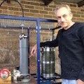
All 4 ion sources have been cleaned and rebuilt and baked out at 200C before instalation. They now use the angled anode rings and SmCo magnets instead of NdFeB magnets for compatibility with Deuterium with out disintegrating, and to allow high temperature operation(up to 300C) without loss of strength. I decided to go with the original style pole piece for now since it provided a near parallel beam with the angled pole piece but may switch over to the other style later. The SmCo magnets have lower field strength though and the ion sources require higher voltage to operate and produce a less intense beam which is fine since they are still significantly over powered for the fusor.

Ion sources before cleaning
SAM_4686a.jpg
In addition, one of the glass disk viewports was replaced with a conflat viewport eliminating one more viton o-ring (5 removed in this modification)
SAM_4691a.jpg
They now use copper o-rings instead of viton and have pump out ducts to avoid virtual leaks.
SAM_4692a.jpg
SAM_4689a.jpg
One of the swagelok valves was outgassing something when it was getting hot and was also replaced, and a 0.5um filter was added to the dry air admit line for venting the fusor to atmosphere for servicing
SAM_4694a.jpg
Some burning on the inside coating of the ZnSe viewports was observed when running with deuterium(doesn't happen with air). There seems to be some charged particle coming from the grid that is not readily deflected by the magnetic beam deflectors. I'm assuming it's a negative deuterium ion
SAM_4695a.jpg
I've doubled the field strength on the beam deflectors by adding a second magnet but it doesn't help much. I may have to remove the ZnSe ports for deuterium runs or re-design them or the grid to deflect the ion beam away from that area.
SAM_4697a.jpg
A feedback control circuit has been built to regulate fusor pressure by feeding back from the vacuum gauge analog output, It will stabiily control pressure from the 1e-4torr range to the 10s of mTorr. This considerably reduces workload during fusion runs and increases neutron output by tracking the optimal pressure. It's a very simple circuit.

Pressure controller circuit
SAM_4698a.jpg
An NP10 boost converter similar to this, or other boost converters used to drive nixie tubes:
http://www.ebay.com/itm/SHV5-5Vin-400Vo ... SwwE5WVDQB
provides 87V from the 24V supply, then an LR12 adjustable regulator steps the voltage down to 70V to feed the positive side of an OPA445 high voltage op amp which is configured as a gain 21 non-inverting amplifier. A recom RS3-1212D DC-DC converter provides -12v to the OPA445 and an AD826 that is used as an input differential amplifier. The vacuum gauge output(quattro 999, 0-10v, logarithmic to pressure) is connected to the negative side, while a potentiometer supplying 0-12v is connected to the positive side. The valve will now accurately control fusor pressure. There is still some drift and overshoot since it's only a proportional feedback controller, but the final version will be a full PID with valve dither ontop of the analog signal to improve performance.
12-5-2015-pressure-control-close.jpg
The fusor will now pump down to the low E-4 range in about 5-10 minutes and max out at about 5e-5 torr after several hours.
12-3-2015-pumpdown2.jpg
The cleaning of the ion injectors and removal of 5 viton o-rings seems to have really helped, though the pressure still climbs when running as the grid insulator heats up. It's made of boron nitride with a boric oxide binder which is fairly hydroscopic and will soak up water every time it sees atmospheric air. It will have to be replaced with a combination of macor/alumina/fused quartz.

Fusion rate is now at 3e5 n/s
12-5-2015-calculations.jpg
Star mode at ~3mTorr during fusion fun
SAM_4704a.jpg
Last edited by Andrew Seltzman on Sun Dec 06, 2015 5:19 pm, edited 1 time in total.
Andrew Seltzman
www.rtftechnologies.org
Post Reply

Return to “Fusor Construction & Operation (& FAQs)”