It’s a work of art Finn!
Did you custom spin the lower flange toroid?
Mark Rowley
Finn Hammer, fusor update.
-
Mark Rowley
- Posts: 909
- Joined: Sun Dec 29, 2002 12:20 am
- Real name: Mark Rowley
- Location: Sacramento California
- Contact:
-
Finn Hammer

- Posts: 298
- Joined: Sat Mar 05, 2016 7:21 am
- Real name: Finn Hammer
- Contact:
Re: Finn Hammer, fusor update.
Mark,
Thanks for your kind words.
The 3 toroids are turned out from solid bar, spinning is something I am looking into, but for this one-off it was simpler to just turn them out of bar stock.
Cheers, Finn Hammer
Thanks for your kind words.
The 3 toroids are turned out from solid bar, spinning is something I am looking into, but for this one-off it was simpler to just turn them out of bar stock.
Cheers, Finn Hammer
-
Richard Hull

- Moderator
- Posts: 15027
- Joined: Fri Jun 15, 2001 9:44 am
- Real name: Richard Hull
Re: Finn Hammer, fusor update.
Wow! You have really documented far better than any others have do on their first pass. The system is plus ultra looking and you have exchanged a lot of money for "the right stuff". I like the field control, but Bar stock!!! You are a better man than I Gunga Din.
Fortunately, we have one of the original Tesla coilers from the first years of the 1989 Teslathon attending regularly to date. He perfected the art of spinning and always shows up at every Teslathon and HEAS October event with toroids for sale at the flea market. Last Year, due to covid, he did not attend, thus, breaking his perfect run over the 32 years of attendance. All of my lab's toroids were spun by John Freau. I think the largest he ever spun was a 10" and the smaller ones like 6 to 4 inch are the ones he normally brings now. He did note that he isn't doing it so much now and only spins a couple for sale at the HEAS flea market. He once sold them by the dozens. We are all getting old now and the tedium of such work for limited rewards is weighed much more seriously as we all have a limited time remaining.
Richard Hull
Progress may have been a good thing once, but it just went on too long. - Yogi Berra
Fusion is the energy of the future....and it always will be
The more complex the idea put forward by the poor amateur, the more likely it will never see embodiment
Fusion is the energy of the future....and it always will be
The more complex the idea put forward by the poor amateur, the more likely it will never see embodiment
-
Finn Hammer
- Posts: 298
- Joined: Sat Mar 05, 2016 7:21 am
- Real name: Finn Hammer
- Contact:
Re: Finn Hammer, fusor update.
Sorry, double post, see below
Last edited by Finn Hammer on Mon May 24, 2021 3:38 am, edited 1 time in total.
-
Finn Hammer
- Posts: 298
- Joined: Sat Mar 05, 2016 7:21 am
- Real name: Finn Hammer
- Contact:
Re: Finn Hammer, fusor update.
Richard,
I have 2 of John Freau's 6 x 1 1/2 inch toroids, and a single 13 inch. Great stuff. John was a regular and very valued contributor to the Pupman list.
I also have tooling for 600mm x 170mm toroids and a good relationship with the spinners shop, so can deliver....
I even had tooling made for reentrant Van de Graaff 400mm top electrodes made. Still some in stock of those too, but the tooling got lost, unfortunately.
It takes 2 pieces of tooling to spin a toroid shell, one for the concave portion, and one for the rest, so if I was going to spin these toroids, I would be looking into even more turning from bar. The tooling can be made from tufnol, or other phenolic types of thermosetting material, but the stench from machining these materials keeps me from doing that, for the most part.
I had planned to make the grid from EDM graphite, but one hole drilled, and a single pass on the bar, on the lathe, convinced me that turning graphite is for another day, when I get a proper point dust extractor setup. Just don't want to foul up the shop with carbon dust.
Cheers, Finn Hammer
-
Richard Hull
- Moderator
- Posts: 15027
- Joined: Fri Jun 15, 2001 9:44 am
- Real name: Richard Hull
Re: Finn Hammer, fusor update.
Great work Finn. I am glad you already have some of John's fine work. I wish you could meet him in person. He is a calm, very retiring and reticent person who is incredibly easy to like. Perhaps if you ever make what few HEAS October events are left in me, you can meet John.
Your effort is one that mimes my own in its temporal journey, which I find the best way to get into fusion. (Slow and easy - Read, do, absorb, correct the do, read some more, do some more, repeat) Of course, you have the best of us to soak up a lot of hard won knowledge. This can shorten the journey, but still, you move at the right pace, taking advantage every wrong thing made right over the years here. It is the right way to do it.
I wish others would enter this way.
Richard Hull
Progress may have been a good thing once, but it just went on too long. - Yogi Berra
Fusion is the energy of the future....and it always will be
The more complex the idea put forward by the poor amateur, the more likely it will never see embodiment
Fusion is the energy of the future....and it always will be
The more complex the idea put forward by the poor amateur, the more likely it will never see embodiment
-
Finn Hammer
- Posts: 298
- Joined: Sat Mar 05, 2016 7:21 am
- Real name: Finn Hammer
- Contact:
Re: Finn Hammer, fusor update.
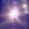
I had first light the other day.
At this point, I knew that the solutions I would come up with would probably have to be altered along the way, possibly in short order, so I allowed myself to delve into the fine art of jerry rigging, the ballast resistor being the first item to receive my left hand attention:
You may be able to see the 3x16 matrix of VR68 resistors, they did not last long......
Next attempt was a 5X10 matrix, this time potted with heat conducting potting in a FR6 tube, it lasted for one hour of testing.
The long thin tube is the voltage divider 1:1000, it seems to be a good one.
One success to report is the voltage control on the feedthrough, it is good.
I had made a squirrel cage grid with 9 pins in it, and this was for the sole reason that I wanted a spanking cool 9star picture as my future avatar, well that turned out to be a bad choise, at least since the axis pointed right at the viewport. I had some bad expectations beforehand, and for that reason I had put sacrifical glass in front of the viewport, this should prove beneficial.
I got my nine star, but in the wrong place, as a blue reflection on the viewport, but what was worse, the front hole in the grid shou out a death ray directly on the glass, which got damaged.
You can see how the glass (quartz) got chips blown out of the surface where the death ray hit.
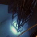
Ok, back to the lathe and make a new grid:
This one showed out to perform better:
and soon It got all red hot.
If I could only figure out how others manage to catch theit fusor internals without all the haze, perhaps it is a photoshop thing
Cheers, Finn hammer
At this point, I knew that the solutions I would come up with would probably have to be altered along the way, possibly in short order, so I allowed myself to delve into the fine art of jerry rigging, the ballast resistor being the first item to receive my left hand attention:
You may be able to see the 3x16 matrix of VR68 resistors, they did not last long......
Next attempt was a 5X10 matrix, this time potted with heat conducting potting in a FR6 tube, it lasted for one hour of testing.
The long thin tube is the voltage divider 1:1000, it seems to be a good one.
One success to report is the voltage control on the feedthrough, it is good.
I had made a squirrel cage grid with 9 pins in it, and this was for the sole reason that I wanted a spanking cool 9star picture as my future avatar, well that turned out to be a bad choise, at least since the axis pointed right at the viewport. I had some bad expectations beforehand, and for that reason I had put sacrifical glass in front of the viewport, this should prove beneficial.
I got my nine star, but in the wrong place, as a blue reflection on the viewport, but what was worse, the front hole in the grid shou out a death ray directly on the glass, which got damaged.
You can see how the glass (quartz) got chips blown out of the surface where the death ray hit.
Ok, back to the lathe and make a new grid:
This one showed out to perform better:
and soon It got all red hot.
If I could only figure out how others manage to catch theit fusor internals without all the haze, perhaps it is a photoshop thing
Cheers, Finn hammer
-
Jim Kovalchick
- Posts: 717
- Joined: Wed Apr 13, 2011 8:00 pm
- Real name:
Re: Finn Hammer, fusor update.
Finn,
Great looking plasma pics!
Regarding haze, fusors tend to look hazy until the chamber conditions through heating. I'm betting yours will look clearer soon.
Jim K
Great looking plasma pics!
Regarding haze, fusors tend to look hazy until the chamber conditions through heating. I'm betting yours will look clearer soon.
Jim K
-
Mark Rowley
- Posts: 909
- Joined: Sun Dec 29, 2002 12:20 am
- Real name: Mark Rowley
- Location: Sacramento California
- Contact:
Re: Finn Hammer, fusor update.
Finn, Ive always had similar problems taking distance shots of the fusor and BoT. Seems that the autofocus latches onto the exterior hardware rather than the slightly more distant plasma within the chamber. My remedy was to place the camera right up against the viewport (using a makeshift insulator) allowing for focus on the grid or BoT target. Sometimes taking a video from the same distance will work better. Then it’s just a matter of taking a screenshot from the video.
Regarding the squirrel cage (SQ) I always wondered how folks kept the axis beam from blasting a divot out of the viewport. The latest videos of Dougs fusor display some great imagery of the SQ in action but there’s no evidence of any beam hitting the viewport. Quite possible there’s a sacrificial lens there but knowing the high power levels he ran I can’t imagine it lasting long. I also can’t imagine him cracking open his chamber all the time to replace it either. It’ll be interesting to find out exactly what he did.
The diameter of your new copper electrode appears to take up a bit of real estate within the chamber. I’m curious if you’ve noticed any problematic interaction with the chamber wall. One of the BoT targets I used which incorporated fixed magnet electron suppression was of similar size. Just big enough to cause a Paschens Law issue with the nearby chamber wall. I know BoT dynamics differ greatly from the fusor but I’ve had similar issues a couple years ago when experimenting with larger fusor grids.
Mark Rowley
-
Finn Hammer
- Posts: 298
- Joined: Sat Mar 05, 2016 7:21 am
- Real name: Finn Hammer
- Contact:
Re: Finn Hammer, fusor update.
Mark, Jim
Regarding the photos, I am stunned. It is not an autofocus thing, I set the focus manually, by shining a flashlight on the grid, so I can see the focus well, camera on a tripod, lens is the famous 200mm Nikon Micro, sharpest lens available. But still there is that blue ionizing thing. I saw it in the big triodes on my single ended tube amplifier too, but not to this extent. I am considering to afd a grounded mesh in front of the sacrifical glass in the viewport.
Regarding the grid diameter, no problems as I see it, no flashovers to ground or anything like that. The first couple of minutes, there was a sort of sprinkling on the surface, as if small specks of dust provoked breakout, but were extinguished in the proces, that is all.
But mind you, I have no idea whatsoever, which diameter is the right one, or more suitable, I use the rule of TLAR ( That Looks About Right) and with my limited experience, that does not say much.
But I did go to the junkyard to get short pieces of stainless tubing in 15 - 22 mm range, and I am quick on the lathe, so many grids will be tested, as soon as I get a suitable ballast resistor. Those power mox resistors look tempting, to end all experimenting on that part.
Cheers, Finn Hammer
-
Frank Sanns
- Site Admin
- Posts: 2123
- Joined: Fri Jun 14, 2002 2:26 pm
- Real name: Frank Sanns
Re: Finn Hammer, fusor update.
Great work on your setup Finn. Top rate.
As for the photos, it is not the camera or radiation. It is a dirty chamber.
Any fusor that is open to the air will have a fog within the chamber. It is outgassing.
If deuterium is added soon after the pump down, the color will look a bit ruddy. This color will clear up rather quickly but the haze can remain for the better part of an hour of operation or even for hours if the fusor was just assembled. Run longer and glow cleaning will clear things up and you will get tack sharp pictures.
The camera is more sensitive than the eye to the haze because of the longer exposure. You may no longer see it but with more light making it into the camera image, it will show up. A good indicator of how clean your chamber is. A necessity before you start getting good neutron numbers.
Achiever's madness; when enough is still not enough. ---FS
We have to stop looking at the world through our physical eyes. The universe is NOT what we see. It is the quantum world that is real. The rest is just an electron illusion. ---FS
We have to stop looking at the world through our physical eyes. The universe is NOT what we see. It is the quantum world that is real. The rest is just an electron illusion. ---FS
-
Jim Kovalchick
- Posts: 717
- Joined: Wed Apr 13, 2011 8:00 pm
- Real name:
Re: Finn Hammer, fusor update.
In addition to the chamber conditioning that Frank and I spoke of, the blue haze could also be your viewport glass fluorescing. Especially with that tube grid, as you noticed, there is a secondary electron beam hitting your glass. Borosilicate fluoresces blue.
-
Mark Rowley
- Posts: 909
- Joined: Sun Dec 29, 2002 12:20 am
- Real name: Mark Rowley
- Location: Sacramento California
- Contact:
Re: Finn Hammer, fusor update.
All good points. Jim, you me minded me of the UV fluorescence on my ion source. Finn, could this be what you’re seeing?
Mark Rowley
- C4C6E860-7356-4A9C-AF04-F5E1038286FE.jpeg (36.34 KiB) Viewed 12232 times
Mark Rowley
-
Richard Hull
- Moderator
- Posts: 15027
- Joined: Fri Jun 15, 2001 9:44 am
- Real name: Richard Hull
Re: Finn Hammer, fusor update.
Great work Finn. I like the photos. Once you get a stable system with a good ballast, you can start smoothing out your operational experience that will become a natural function of your hands at the controls. once you are in the groove, you will become extremely sensitive to any sudden changes in operational characteristics. Smooth stability in startup and running is the goal. Early on, a fusor can be all over the place. Every time you open the system or change a grid, it is a whole new ball game, starting from scratch and having to get use to new characteristics.
Richard Hull
Richard Hull
Progress may have been a good thing once, but it just went on too long. - Yogi Berra
Fusion is the energy of the future....and it always will be
The more complex the idea put forward by the poor amateur, the more likely it will never see embodiment
Fusion is the energy of the future....and it always will be
The more complex the idea put forward by the poor amateur, the more likely it will never see embodiment
-
Finn Hammer
- Posts: 298
- Joined: Sat Mar 05, 2016 7:21 am
- Real name: Finn Hammer
- Contact:
Re: Finn Hammer, fusor update.
Frank,
Thanks, good news if a dirty chamber is the reason, dince there is s remedy for that.
I had gotten sloppy with the chamber cleanliness, time to take it apart for a vigorous rubdown.
Mark,
UV flourescence sounds about right.
Jim,
The sacrifical glass is quartz, I forget whar the Lesker viewport has.
Cheers, Finn Hammer
-
Finn Hammer
- Posts: 298
- Joined: Sat Mar 05, 2016 7:21 am
- Real name: Finn Hammer
- Contact:
Re: Finn Hammer, fusor update.
The ballast resistor.
There are some chinese wirewounds that claim to stay within spec. both voltage- and powerwise, but given the urgency (which is, of course, more imaginary than real) and a bit of scepticism, combined with previous excellent experience with Ohmite's products, led me to the conclusion that there is really only one possible candidate for a ballast resistor, as aquired across the counter, and it is one out of the Power-mox series, from Ohmite.
Mouser has them, and the item shipped free from the US to Denmark, but then it is not exactly cheap either.
I have no doubt that it is worth every penny, now that it has been in my hands for a couple of days. This is what quality looks like:
Now, it does not come in the funky non-inductive style that "they" parade on their product page, because it is what we all would want if it was available,
but apart from that, it is everything desirable, ceramic former, thick film resistive spiral and the coolest clear lacquer finish. And the 11 turns work out to 0.3µH, so what.....
Only complaint is the radial attachment lugs, I don't like them. Lots of sharp pointy edges, lots of places for corona to form. Corona, the dreaded mother of all arc discharges, the culprit of every surface track. Something had to be done, and what.. isn't that why I made that radius attachment to my lathe? so that I could whip up a nice couple of toroids in short order?
After another day in the workshop, this is what I had available:
The toroids are mounted to the resistors collet style, not unlike some potentiometer buttons attach to the shaft (the good ones that don't mar the spindle with set screw marks) and some phenolic and FR4 trimmings to suspend the assembly.
The finished article looks like this:
The rated power dissipation as I^2 x R losses is 50W, so it can support a continious current of 31mA to flow
The ballast resistor only sees the full voltage across the element for a brief flash in time, just when the arc strikes, otherwise the voltage drop is a maximum of 5000 x 0.031 = 158V,
(Edit: woops, should have read 50000, not 5000, for 1580V)
but the whole structure will be floating at whatever voltage I dare to throw at it, and since I don't want to use oil, and neither want it to arc to surrounding grounded parts, that is the reason for this litle exersize in field control.
The fact that it is also pleasing to the aestetic senses is only an added bonus.(Us seasoned tesla coil builders have an incurable, weak spot for toroids).
Cheers, Finn Hammer
There are some chinese wirewounds that claim to stay within spec. both voltage- and powerwise, but given the urgency (which is, of course, more imaginary than real) and a bit of scepticism, combined with previous excellent experience with Ohmite's products, led me to the conclusion that there is really only one possible candidate for a ballast resistor, as aquired across the counter, and it is one out of the Power-mox series, from Ohmite.
Mouser has them, and the item shipped free from the US to Denmark, but then it is not exactly cheap either.
I have no doubt that it is worth every penny, now that it has been in my hands for a couple of days. This is what quality looks like:
- Quality!
Now, it does not come in the funky non-inductive style that "they" parade on their product page, because it is what we all would want if it was available,
- Funky but non-stock!
- Power_Mox_DSL.jpg (14.42 KiB) Viewed 10615 times
but apart from that, it is everything desirable, ceramic former, thick film resistive spiral and the coolest clear lacquer finish. And the 11 turns work out to 0.3µH, so what.....
Only complaint is the radial attachment lugs, I don't like them. Lots of sharp pointy edges, lots of places for corona to form. Corona, the dreaded mother of all arc discharges, the culprit of every surface track. Something had to be done, and what.. isn't that why I made that radius attachment to my lathe? so that I could whip up a nice couple of toroids in short order?
After another day in the workshop, this is what I had available:
The toroids are mounted to the resistors collet style, not unlike some potentiometer buttons attach to the shaft (the good ones that don't mar the spindle with set screw marks) and some phenolic and FR4 trimmings to suspend the assembly.
The finished article looks like this:
The ballast resistor only sees the full voltage across the element for a brief flash in time, just when the arc strikes, otherwise the voltage drop is a maximum of 5000 x 0.031 = 158V,
(Edit: woops, should have read 50000, not 5000, for 1580V)
but the whole structure will be floating at whatever voltage I dare to throw at it, and since I don't want to use oil, and neither want it to arc to surrounding grounded parts, that is the reason for this litle exersize in field control.
The fact that it is also pleasing to the aestetic senses is only an added bonus.(Us seasoned tesla coil builders have an incurable, weak spot for toroids).
Cheers, Finn Hammer
Last edited by Finn Hammer on Sun Jun 06, 2021 1:53 pm, edited 1 time in total.
-
Richard Hull
- Moderator
- Posts: 15027
- Joined: Fri Jun 15, 2001 9:44 am
- Real name: Richard Hull
Re: Finn Hammer, fusor update.
Even in a dangerous pulse of current the voltage across the resistor will not reach a level to arc running end to end on the resistor, the voltage is near zip. At a run current of 20ma you are looking at 1kv across the resistor. (50,000 X.02 = 1000volts) The resistor would internally arc band to band, (assuming zero supply impedance), long before it would arc toroid to toroid in a pulse condition.
Unfortunately, there is the real impedance of the supply thrown in, buckling the output voltage and the plasma arc impedance within the arcing fusor. This limits arcing possibility within in the ballast resistor.
Still, you have closed all possible doors with this overkill. Slick, polished insulation on flat surfaces accumulate dust to create paths not expected. Those toroids are awful close to that surface.
Richard Hull
Progress may have been a good thing once, but it just went on too long. - Yogi Berra
Fusion is the energy of the future....and it always will be
The more complex the idea put forward by the poor amateur, the more likely it will never see embodiment
Fusion is the energy of the future....and it always will be
The more complex the idea put forward by the poor amateur, the more likely it will never see embodiment
-
Finn Hammer
- Posts: 298
- Joined: Sat Mar 05, 2016 7:21 am
- Real name: Finn Hammer
- Contact:
Re: Finn Hammer, fusor update.
Richard,
You see it all.
The dust is one aspect that I had not given any consideration, and although the assembly is being mounted upside down, with the resistor hanging, there is no telling what electrostatic forces can do to throw dust upwards.
I may have to redesign the FR4 standoffs for more clearance.
Cheers, Finn hammer
-
Dennis P Brown

- Posts: 3189
- Joined: Sun May 20, 2012 10:46 am
- Real name: Dennis Brown
Re: Finn Hammer, fusor update.
I submerged my ballast resistor under oil; fully synthetic auto oil since that is actually superior to many transformer oils. It not only electrically insulates it but dissipates heat significantly better than air.
-
Richard Hull
- Moderator
- Posts: 15027
- Joined: Fri Jun 15, 2001 9:44 am
- Real name: Richard Hull
Re: Finn Hammer, fusor update.
When checking out my x-ray transformer back in 2004 before installing it in the fusor IV rack system, I put my 63kohm, 100W ballast resistor in the tank with new HV silly cone diodes all in the oil. There it has resided for the last 17 years along with the diodes. Once pulling out the vacuum rectifiers and filament xfrmr back then, there was a lot of room for the new diodes and ballast.
Richard Hull
Richard Hull
Progress may have been a good thing once, but it just went on too long. - Yogi Berra
Fusion is the energy of the future....and it always will be
The more complex the idea put forward by the poor amateur, the more likely it will never see embodiment
Fusion is the energy of the future....and it always will be
The more complex the idea put forward by the poor amateur, the more likely it will never see embodiment
-
Finn Hammer
- Posts: 298
- Joined: Sat Mar 05, 2016 7:21 am
- Real name: Finn Hammer
- Contact:
Re: Finn Hammer, fusor update.
Arriving back from Copenhagen, from my 9 day masonry assignment, one of the first things to do, was to bring the cube back to life.
I had left it with all valves closed, and pumped it down below 1E-5, which is the lowest reading on my current transducer, a 901P.
Immediately, I started to introduce deuterium, and settled for 22microns, then cranked up the voltage.
Getting stable operation is a breze, and soon it was running at 20 microns, 29kV and 12mA to produce, after 4 min. run, 700CPM on the Ludlum model 3 with the 44-9 frisker probe.
I did 3 more runs, finishing with a 10 minute run which was particularly good, because I found out how to bring the beast up to power slowly, which surprisingly made it possible to operate at 24 microns, 29kV and exeeding 15mA with the grid getting only a dull red. This produced in excess of 1000CPM.
The Canberra dosemeter started to report 500 microroentgen, so I stopped the operation of the fusor for this part, untill leadshielding is in place, and the Ludlum Model nine has arrived. At that time, I will swap the 30kV multiplier to a 60kV unit, and try not to break the feedthrough.
Edit. Changed CPS to CPM, these being counts from the silver foil made off a 1/4 piece of a silver dollar, hammered out.
Cheers, Finn hammer
-
Richard Hull
- Moderator
- Posts: 15027
- Joined: Fri Jun 15, 2001 9:44 am
- Real name: Richard Hull
Re: Finn Hammer, fusor update.
Finn, Great system! I retain a leaky fusor and can't restart as rapidly as many with a very tight system. I am sure it is due to my HV feed through. I am envious of those who can instantly restart a fusor to max function after a week or more of being left fallow, but sealed off. You have done great work and it shows. I need a minimum of three consecutive days of "conditioning" to obtain top level function. After that the next day I can blast right up in mere minutes as reported a few weeks back. A single week of inactivity will force at least two days to recondition. A month or more will need three days and 3 months, about 4 days. Just be glad you have a system that is well sealed.
As you know I created a nice little Arduino box slung under my fusor and imbedded a GM tube with silver or Rhodium wrapped around the tube in my 3He neutron detector moderator. I had the Arduino count for 10 seconds and record the count and sent the total to Arduino EEPROM memory. Then it counted again for 10 seconds and stored in the next EEPROM cell and so on. (This counting is initiated the instant the fusor is shut down) Then using the serial monitor in the Arduino IDE, I transferred, (dumped) the stored EEPROM data as a simple text file to a laptop via the USB port on the Arduino. I next blew the comma delimited text file into Excel to create a nice graph of the decay curve. Worked out great. I later changed the count period to 5 seconds. (only had to change one line of code). I will note that due to the variability of short 5 second counts in my rather noisy lab background, the curves look a lot better if my fusor is cranking out 7.5e5 or more n/s TIER during the activation period.
There are so many cool things one can do like this. Naturally, you can no longer swap, with any ease, activation materials by doing the above, but it does allow for two detection methods in one moderator i.e., electronics and activation which can be seen and proven in a demonstration rather quickly. One can still have a "neutron oven" near the fusor for rapid swapping of different elements for activation if desired.
I just found it interesting rather than to demo my fusor with a screaming electronics neutron counter, while doing fusion, to show that the instant the reactor was cut-off, (dead), have a new count now issuing from a radioactive neutron activated element which the neutrons created and to see the decay plot match the decay curve predicted. Many folks do not demo their reactors on a regular basis. I spend many moments demonstrating my fusor for interested persons and groups. I found activation a great way to prove to skeptics that I had done fusion. I often find that a person or people I demo the system to will tell others who are incredulous and unbelieving. This will usually setup yet another demo, in future.
Richard Hull
Progress may have been a good thing once, but it just went on too long. - Yogi Berra
Fusion is the energy of the future....and it always will be
The more complex the idea put forward by the poor amateur, the more likely it will never see embodiment
Fusion is the energy of the future....and it always will be
The more complex the idea put forward by the poor amateur, the more likely it will never see embodiment
-
Finn Hammer
- Posts: 298
- Joined: Sat Mar 05, 2016 7:21 am
- Real name: Finn Hammer
- Contact:
Re: Finn Hammer, fusor update.
With the 60kV greinacher in place, I did a 4 minute run at 40kV today, 25 micron and averaging 15mA, to do activation of 90% silver/10% copper, from my crummy piece of hammered out silver dollar.
This produced 2400 CPM on the 44-9 frisker probe. This is a new record for me.
It is interesting that the tube cathode seems to heat up to a lesser degree at 40kV than at 30Kv, same current, I would have guessed the opposite, not that I am complaining.....
A new instrument came in the other day:
With this in hand, I could measure the radiation from the running fusor, and at 30kV, 20mA it generates 0.4mRoentgen/hour at 2 feet distance from the front face of the fusor.
This was without lead shielding, however the viewport has a quarter inch of lead glass. this glass is the equivalent of 1.6mm lead, which I was able to confirm by exchanging it with a piece of lead that thickness.
Running the fusor without the leaded glass, the radiation shot up to 3.6mRoentgen/hour.
I am waiting for this book to arrive:
Radiation Detection and Measurement
Glenn F. Knoll
Simply because it is not at all obvious how the different units relate to each other. I do know there is a factor of 100 between roentgen/hour and sieverts/hour, so that 0.4 mR/Hour translates to 4µS/Hour, and using this chart:
I deduce that 10 hours of fusion will put me square with a traveller by plane from NY to LA, which should not pose any concerns. For now, at least.
How to get from Sieverts to REM is another ballgame, but hopefully the mentioned book will fill me in on that aspect.
Anyway, nice to run and tweak the fusor.
If I should say something central about the cube fusor/cylindrical Kathode configuration it is this:
The cylindrical Kathode will quite possibly save the newcomer from one inevitable setback of the traditional grid: The meltdown.
The possibility of including water cooling of the body and endcaps at design time means that the fusor can run for hours on end without overheating. I have done 20minutes at full bore, with only a 15 degC raise of temperature.
But to get the best of these two hardware features, the access to -and ability to operate- a lathe, is mandatory.
Cheers, Finn Hammer
-
Rich Feldman

- Posts: 1471
- Joined: Mon Dec 21, 2009 6:59 pm
- Real name: Rich Feldman
- Location: Santa Clara County, CA, USA
Re: Finn Hammer, fusor update.
Belated applause for the ballast resistor with anti-corona toroids on the ends. They are solid aluminum, right?
A work of art and science!
I was reminded of it last weekend in San Jose, California (at 4th and Taylor).
Perhaps for safety around the exposed neon, which had been left "on" that summer afternoon.
A work of art and science!
I was reminded of it last weekend in San Jose, California (at 4th and Taylor).
All models are wrong; some models are useful. -- George Box
-
Finn Hammer
- Posts: 298
- Joined: Sat Mar 05, 2016 7:21 am
- Real name: Finn Hammer
- Contact:
Re: Finn Hammer, fusor update.
Rich,
Noticing things like that is a sure sign of highvoltageitis. I suspect many of us have it. Thanks to god, we don't have to suffer from it.
Below is the present lash up, I am starting to see the wisdom in having the high voltage feedline coming down from above.
Cheers, Finn Hammer
Noticing things like that is a sure sign of highvoltageitis. I suspect many of us have it. Thanks to god, we don't have to suffer from it.
Below is the present lash up, I am starting to see the wisdom in having the high voltage feedline coming down from above.
Cheers, Finn Hammer