DAQ / Control System
I made a new control box that has hardwired connections for voltage, current, and MFC deuterium flow. The signals are passed through 100ft of 15-core, stranded, shielded wire running alongside a fiber optic cable. Fiber to ethernet converters on either end connect to a computer and an Arduino Ethernet shield to allow for data collection. The Arduino drives four ADS1115 16-bit ADC modules that monitor pressure and neutron production rate, and soon will also measure deuterium flow, and several other variables. My Spellman power supplies are also connected over ethernet for voltage and current monitoring. Values are periodically sent through the fiber and a custom Matlab GUI parses, displays, and saves the values. There are still several bugs to work out, most notably that the Arduino is EMI-sensitive. I also replaced the needle valve with a 15sccm MFC which gives superior (and remote!) pressure control with the turbo throttled. The voltage, current, and deuterium flow are hard-wire-controlled through the cable and a control box. I can now comfortably sit up to 100ft away from the device, should I desire.
- Version 3 of the data acquisition system
- Don't look, it's pretty ugly...
- 15-conductor and fiber umbilical cable, 100ft
- MFC
- Control box
Power Supply
I obtained a second Spellman DXM70N600 power supply off Ebay in working order. With the help of some engineers from Spellman, I replaced the DXM firmware with SLM firmware. This allows the supplies to regulate against voltage and current setpoints rather than shutting off upon exceeding them. They work in parallel as a simple master-slave system with both voltage programming lines connected in parallel and the master current monitor driving the slave current programming line. The setpoints are controlled through the aforementioned 100ft cable. I 3D printed custom connectors for both supplies and potted them with RTV silicone. The outsides of the connectors accept o-rings and are packed with silicone grease to prevent arcing. So far I've had no issues at >50kV. (Edit: One connector arced along the length of the cable and now has to be replaced. Voids in the silicone are to blame.) The HV cable is standard RG-58U with the shield pulled ~8" back from the ends. Each supply connects to separate 200k resistors and 100kV diode strings before joining at the HV feedthrough. This configuration allows me to run the system at up to 16mA, but I usually keep it below ~8mA to reduce heating. I only push it higher for short runs measured in the tens of seconds. The grid and chamber get very hot very quickly at high currents which cause the neutron production rate to plummet (wall/grid loading, I presume).
- Not proud of the floating HV components, but it works ok
- 3D printed connector
Feedthrough
I made a couple changes to the vacuum end of the HV feethrough. The ceramic washer that was designed to shield the quartz from direct plasma bombardment has sputtered full of material and now arcs profusely at anything above 25kV. I retracted the quartz and added an alumina stalk for the last few cm. More arcing then forced me to forego all ceramic and leave the stalk bare. Like I mentioned in the dedicated design thread, this new version works flawlessly.
- New feedthrough
Gamma Spectroscopy
I made a 3" NaI(Tl) detector using a Photonis PMT and crystal from Russia. The housing is 3D printed PLA. I use an old Ludlum Model 12 set to 1100V as the HV supply and for simple count-rate measurements. Background is ~20kCPM. My poor-man's MCA, if you ignore the $500 scope (Siglent SDS1104X-E), is as follows: I tapped into the the model 12 circuit directly behind the HV capacitor and passed the signal through the housing with a BNC connector. This connects to an oscilloscope which then interfaces with a computer via Ethernet. With the scope set to 100-200ms/div, a Matlab script queries the scope for the waveform data. The 14Mpts worth of data are then filtered in-software, peaks are located and binned, and then a histogram is displayed. I get about 7% FWHM resolution for 137Cs and can detect x-rays down to ~15kV before the noise floor interferes. It easily picks up x-rays from the fusor, and I've confirmed the calibration using 241Am, 176Lu, and background K40.
- Gamma spectrum with oscilloscope MCA
- Custom 85x60mm NaI(Tl) probe
X-Rays
I picked up a CD V-742 dosimeter from a Hamfest a while back and have been placing it at the fusor viewport behind the lead shielding. It read zero when I got it but is now at 60 roentgen. Yikes. Keep those shields up.
- Dosimeter
Breaking the Mega Mark
I am reasonably confident that I hit 1e6 n/s the other day while pulsing the system at higher currents. Since the system heats up very quickly and neutron rates drop, I was limited to ~5s runs. I verified that my neutron detector, which is simply a SNM-17 tube surrounded by paraffin coupled to a Ludlum Model 12, is immune to fusor noise using the standard moderator-removal test. I waited for the needle to stabilize for a few seconds before recording the CPM. The detector axis is just 13.5cm from the poissor, so given the anisotropy from beam-target fusion and the neutron-emission resulting from a single-beam grid, the results should be taken with a grain of salt. The three most impressive runs are as follows:
28kV, 12mA, 13.3mtorr, 100kCPM, 3.4e5n/s, Q=1.13E-09
37kV, 14mA, 17.0mtorr, 200kCPM, 6.7e5n/s, Q=1.49E-09
37kV, 11mA, 14.3mtorr, 300kCPM, 1.0e6n/s, Q=2.86E-09
33kV, 11mA, 17.0mtorr, 350kCPM, 1.2e6n/s, Q=3.66E-09
43kV, 15mA, 17.0mtorr, 300kCPM, 1.0e6n/s, Q=1.84E-09
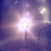
I found that the neutron production rate was heavily dependent on grid temperature, which is why the 43kV and 37kV runs were less successful. I did not give the system adequate time to cool. Also, the rotation of the grid and symmetry with respect to the 6-way conflat arms was critical. I did my best to align the grid holes with the chamber axes. On these runs only a single bright beam formed along the long chamber axis (extra conflat crosses, while the other axis has blanks), although a very faint orthogonal beam is visible.
- Single beam
I realize that the voltages are rather low for this kind of output, and perhaps the higher currents compensate, but I have not found any sources of noise. I was able to achieve rates between 3e5 n/s and 1e6n/s for two days until an unrelated issue forced me to shut down and open the chamber. Due to the semi-repeatability, I doubt it's simply Poisson noise, and detector pileup isn't an issue at these count rates. I should have moved the detector and verified an inverse-square relation, but such is high voltage safety and hindsight.
Chamber Reconfiguration
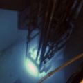
My 6-way chamber was nestled between other conflat components which made shielding difficult and the entire thing difficult to access. I reconfigured the vacuum system, put the chamber above the frame, and subset the rest of the parts below. Now 5 of the 6 sides are available for the feedthrough and viewport, leaving 3 blanked-off for whatever comes next.
- Chamber above and vacuum system below, HV feedthrough off for maintenance
I took the opportunity to replace the viewport and sacrificial glass. The latter is chipped and sputtered brown, and since I previously used the viewport without protection, it has degraded as well. Since I didn't properly mount the sacrificial glass, it rested on the bottom of the tube and led to the following:
- Offset section of glass protected from sputtering
- Chipped sacrificial glass
The new viewport is better protected by a new glass disc, which is now held in place using expandable metal sleeving.
- New viewport
Indium Activation
After reconfiguring the chamber, I activated a piece of indium foil. It was placed between two paraffin blocks at one of the end caps and irradiated for 1-2 minutes at 1e5-3e5 n/s. Count rates on a 2" pancake were between 180 and 300 CPM and quickly decayed to background. I haven't yet taken a gamma spectrum nor irradiated the foil for longer due to chamber heating. The chamber reaches well over 100C after just a couple minutes, and I prefer to keep my viewport intact.
- Indium foil
Some miscellaneous pictures:
- Neutron detector. Wires bridge analog meter for neutron reading by DAQ.
- Pressure gauge for monitoring remaining deuterium
- Feedthrough broken by my idiocy, not heat or HV.