Alright, although I would like to build a true RF ion source some day (thank you for correcting me about the difference bewteen magnetron and RF), I think the hot cathode idea will be the simplest for my first ion gun. Is this just a tungsten filament running across a feedthrough at a couple amps? If it is, will this filament work, because I would rather not expose myself to beryllium dust trying to cut open a microwave magnetron.
model OB-3 from
http://www.tungsten.com/orphan.html
Also, does the deuterium have to be running directly through the filament, or can the gas inlet be mounted on another port?
Magnetron Ion Gun
-
Doug Coulter

- Posts: 1312
- Joined: Sun May 27, 2007 3:18 pm
- Real name: Doug Coulter
- Location: Floyd, VA, USA
- Contact:
Re: Magnetron Ion Gun
One of the ion sources I used to make a gage was simply a filament from a tiny quartz halogen bulb (6v 12W from a lawn ornament) that I cut the top off of (diamond wheel on the lathe tool post grinder). As tungsten is a lousy emitter of electrons without some help, I tried both the Ba/Sr/Ca carbonate mix they use for electron tubes (which decomposes at high temps to Ba0 etc which is what really does the emission), and a Y2O3 coating, which is what I stuck with so I could run it yellow hot instead of hotter -- the Ba mix doesn't like being exposed to air once activated, and only lives about 3 times of that before it won't reactivate, while the Y2O3 doesn't have that problem. With about 70-100v on the "anode" electrode, this gave some good electron current and reasonable filament life -- tungsten really doesn't like being run with even trace amounts of water present, and quickly dies -- and all vacuum systems do have some water as the main contaminant unless very heroic measures are taken. This is why exotic materials are used in mass spectrometer filaments -- the assumption is that you're going to be measuring something other than perfect vacuum, and in less than perfect vacuum (or inert gas only) tungsten just doesn't live long.
If you can afford it, the high alloy wire from type C thermocouples makes a much more robust filament (26% Re) that doesn't have the water disease nearly as badly. The fat 2 amp filament in the bulb does go bad at some point, even though it's running at much less than ratings. You can get that thermocouple wire pretty thin so it doesn't need as much current to light up, say 5 mils or so. The high Re content also makes it lots less brittle so you won't get as frustrated with it breaking when you try to form it.
The reason I let gas in right through my sources is that in molecular flow vacuum levels, that's there the pressure is highest and the gas easiest to ionize well. No particular other reason, its a minor "tweak" on something.
FWIW, for a non RF ion source I suspect the one championed by Andrew Seltzman may be best.
But I haven't tried it myself. Look here for details, for some reason I couldn't find the thread here on this board.
http://www.rtftechnologies.org/index.htm
Other tricks I've tried include ionizing the gas right at an inlet orifice while it is still at high pressure, and easy to ionize with low voltages. The problem with that one was the insanely tiny clearances (less than .01") needed to get to the gas before it expanded to low pressure, and the sputtering onto insulators nearby. Another was the typical magnet crossed field source, called a magnetron in an overload of that word to mean too many different things, IMO. Sputtering killed that one too. In either case, a few more revs of mechanical design so that all insulators were shadowed from sputtered metal vapor may have made them acceptably reliable, but I got disgusted and came up with my RF one that is really only a slight improvement on an older design in Rev Sci Instruments.
For those who don't know, here's the tungsten disease:
Hot tungsten disassociates water vapor on the surface. The resulting oxygen oxidizes the tungsten. Tungsten oxide has a low boiling point and flies off. When it hits the tank or bulb walls, it is reduced by the hydrogen, and water results again. Repeat till filament burns out. This preferentially happens at the place it's hottest, and thinnest already. This is one reason the early incandescent bulbs didn't use tungsten...they couldn't get the lamps free enough of water to make them reliable. The other was I suppose that tungsten wasn't either cheap or readily available then -- but even iridium was tried, and that has neither property itself, nor does osmium.
Halogen bulbs reverse this process. Tungsten evaporates some, and is combined with the iodine or other halogen. At heat, this decomposes back into tungsten and iodine again, which happens at the hottest and thinnest part of the filament. Unlike all other filament bulbs, this actually means the life is shorter if they are run below design temperature! At design temperature, they are somewhat self repairing! They have to run hot to work, and with that halogen, you have to have a quartz bulb, so "quartz halogen" is nearly one word in the lamp business.
Why guess when you can know? Measure!
-
Steven Sesselmann
- Posts: 2128
- Joined: Wed Aug 10, 2005 9:50 pm
- Real name: Steven Sesselmann
- Location: Sydney - Australia
- Contact:
Re: Magnetron Ion Gun
Ethan,
You can build a a power supply from microwave junk.
The heater coil on a MOT is perfect for heating the filament, and you can rectify the HV coil with one diode, to use for the negative bias.
The filament runs at about 4-6 volts to glow orange, and the bias needs to be around -1400 volts. You then feed the gas in through the filament, the gas is then stripped of electrons as it passes through the planar stream of electrons. A very efficient ion source.
Note1, It needs good cooling!
Note2, Never heat the filament in air, it will burn out immediately.
Note3, Be careful, Microwave Oven Transformers are dangerous, dont play with them unless you know what you are doing.
Steven
http://www.gammaspectacular.com - Gamma Spectrometry Systems
https://www.researchgate.net/profile/Steven_Sesselmann - Various papers and patents on RG
https://www.researchgate.net/profile/Steven_Sesselmann - Various papers and patents on RG
Re: Magnetron Ion Gun
Ethan
It is better to run the gas through the filament - the idea is to strip as many Electrons as possible and no better way than to make them pass through the hot filament and stream to the anode - this is what makes the Starfire so efficient.
It is better to run the gas through the filament - the idea is to strip as many Electrons as possible and no better way than to make them pass through the hot filament and stream to the anode - this is what makes the Starfire so efficient.
Re: Magnetron Ion Gun
Ok, so to make a power supply for this out of a MOT, do I just keep the original circuit intact, but remove the capacitor and place a wire between these connections, the magnetron in the picture being replaced with a filament across the two leads? Also, where can I get yttrium oxide coating, and do I really need it?
- Attachments
-
- doubleranim_a.gif (8.12 KiB) Viewed 9989 times
Re: Magnetron Ion Gun
Found the yttrium oxide from rare earth products for $27 25g. How exactly do you coat tungsten with this, just run it through the powder?
-
Steven Sesselmann
- Posts: 2128
- Joined: Wed Aug 10, 2005 9:50 pm
- Real name: Steven Sesselmann
- Location: Sydney - Australia
- Contact:
Re: Magnetron Ion Gun
Ethan,
You need to rearrange the MOT parts slightly.., and forget the Yttrium Oxide, when the filament glows orange, it emits more electrons than you can handle.
The attached Diagram shows a simple rearrangement of components, you may put a high ohm ballast resistor between the filament and the MOT HV, to prevent over current.
Steven
PS: Attached diagram originally from John Hendron
- Attachments
-
http://www.gammaspectacular.com - Gamma Spectrometry Systems
https://www.researchgate.net/profile/Steven_Sesselmann - Various papers and patents on RG
https://www.researchgate.net/profile/Steven_Sesselmann - Various papers and patents on RG
Re: Magnetron Ion Gun
Ethan
Your circuit shown will short on alternative half cycles if you short the cap as shown - the current will simply pass through the diode on half cycles - better to use the circuit as shown by Steven - it will rectify half wave and with the cap will produce DC albeit noisey
Your circuit shown will short on alternative half cycles if you short the cap as shown - the current will simply pass through the diode on half cycles - better to use the circuit as shown by Steven - it will rectify half wave and with the cap will produce DC albeit noisey
-
Doug Coulter
- Posts: 1312
- Joined: Sun May 27, 2007 3:18 pm
- Real name: Doug Coulter
- Location: Floyd, VA, USA
- Contact:
Re: Magnetron Ion Gun
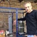
Here's a pic of a working ion gage I made, same idea more or less. Those are two 6v, 2a bulbs I busted to get the filaments -- nice trick, and they're already mounted up well and very rugged. I used two bulbs so I could compare two coatings, or coated vs uncoated on a single vacuum run.
Pure W does NOT emit well at all at orange, Steven must either have had thoriated tungsten or a coated filament without knowing it. Plus, I bet that what's really happening is a bit of plain thermal ionization which starts a garden variety gas discharge going, then when ions hit the filaments there is secondary emission that knocks out several more electrons per strike. You don't get even a microamp emission at orange heat from pure W, I know, I've measured, and besides, about a century of practice in the design and making of electron tubes backs this up -- see almost any old EE book that mentions things like this, I like the 1943 Terman book or one of RCA's tube design handbooks (they printed up some internal documents to bring their own designers up to speed, I am not talking about the tube *users* book here). Sorry Steven, you're just dead wrong on this one. It may work for you, but not for the reasons you think.
Here's a little background, but the tube design handbooks you can access at the link I gave Steven have a lot more.
http://en.wikipedia.org/wiki/Thermionic_emission
The circuit they are showing doesn't have a current limit, and you're going to have problems with that. Normally the series cap in a maggie oven volt doubler is what limits current. With the circuit shown you're going to have to have some other current limit or there's going to be smoke. The maggie transformer is designed to core saturate at about 89-92 volts input and will get very hot at full input even with no load, by the way, so here I either use a variac or a 100-200 watt 120v bulb in series with the primary. Even in an oven (and under full load the saturation is less) they don't run all day long, just minutes, and that with a big fan on them....so watch for that. Also, with too much current input, the thing will go negative resistance on you, finally limiting out at arc welding kinds of speeds and feeds -- about 20 volts at horrendous amps jumping an inch gap and evaporating metal.
So you do need some current limit in there....gas discharges are pretty complex and have taken up several entire careers of smart people, and we still don't know it all.
Here's a link to some of this info:
http://www.coultersmithing.com/OldStuff/pdfs/dox.html
The ideal voltage for making ions is in the 70-150 volt range, ask any ion gage or mass spectrometer.
(Dustin, do you have a comment here?) At 4kv the cross section is much lower -- the electrons whiz by the gas atoms too fast to do much.
I'm pretty sure that something else is going on there, not straight electron ionization of gas, but hey, it may work fine -- anything that gets to drawing some current will....The main thing to look at is how wide a range of gas pressures it will work over.
Yes, you can just make a slurry in water of the coating and drag the filament through it, or use a little bitty paint brush. I use cataphoresis which is what the pros do, mainly to learn how, and it does work better.
To do that (should you need to) you put the thing in a beaker with the stuff, agitated as it doesn't dissolve, with real pure (store distilled is good) water and put perhaps 70-100 volts negative on that, with positive on an anode -- I use a little piece of the same lead sheet I use for rad shielding, but a lot of things would work. You'll see a couple of milliamps, and this drives the stuff right into the pores in the tungsten -- it really stays on. You only need just about enough to see, too thick and in insulates and then falls off. Pure water is actually a pretty good insulator, if you have a clean setup you won't draw a lot of current or see bubbles. A fleck of dust will make it not pure, though.
If you're somewhere where there's not a scary customs barrier, I can mail you a little of the Y2O3, I have a pound, and a gram does about 50 of these. I don't want to mail some white powder to someplace they'll think it's anthrax or coke.
BTW, the .005" diameter wire from type C thermocouples, the high Re one, also works well and lasts longer than pure tungsten does, as the Rhenium prevents the water/tungsten cycle. Expensive but you may be able to scrounge a little somewhere, and you don't need much.
Here's a gif from the Terman book. This is correct beyond any question. FWIW, 1000C or 1273K is very high up in the yellow heat range. Orange is around 800C....Most electron tubes operate around 700C or so with coated filaments, and thoriated tungsten is mostly used around 1000c.
- Attachments
-
-
Why guess when you can know? Measure!
-
Chris Bradley

- Posts: 2930
- Joined: Fri May 02, 2008 7:05 am
- Real name:
Re: Magnetron Ion Gun
What does "magnetron" in this diagram mean? I'm a bit confused - seems to be a magnetron without its magnets, nor cathode and anode either?
-
Steven Sesselmann
- Posts: 2128
- Joined: Wed Aug 10, 2005 9:50 pm
- Real name: Steven Sesselmann
- Location: Sydney - Australia
- Contact:
Re: Magnetron Ion Gun
Chris,
Not sure which diagram you are referring to, but to clarify the Starfire ion source merely uses the filament and power supply "from" a commercial magnetron, as it happens to be the perfect shape and very robust. So not a magnetron per se.
Steven
Not sure which diagram you are referring to, but to clarify the Starfire ion source merely uses the filament and power supply "from" a commercial magnetron, as it happens to be the perfect shape and very robust. So not a magnetron per se.
Steven
http://www.gammaspectacular.com - Gamma Spectrometry Systems
https://www.researchgate.net/profile/Steven_Sesselmann - Various papers and patents on RG
https://www.researchgate.net/profile/Steven_Sesselmann - Various papers and patents on RG
-
Chris Bradley
- Posts: 2930
- Joined: Fri May 02, 2008 7:05 am
- Real name:
Re: Magnetron Ion Gun
It was a post under (and in respect of) Ethan's, with "magnetron" printed on his image.
-
Carl Willis

- Posts: 2841
- Joined: Thu Jul 26, 2001 7:33 pm
- Real name: Carl Willis
- Location: Albuquerque, New Mexico, USA
- Contact:
Re: Magnetron Ion Gun
Chris:
"Figure 2A" represents the standard circuit of a household microwave oven.
The magnetron tube is depicted as a high-vacuum diode, of which it is a variant.
-Carl
"Figure 2A" represents the standard circuit of a household microwave oven.
The magnetron tube is depicted as a high-vacuum diode, of which it is a variant.
-Carl
Re: Magnetron Ion Gun
Doug, you say that the ideal voltage is 70-150v? Doesn't a magnetron filament transformer only produce 3-6v (with the 2kv bias)? Yes, I do have a variac to limit current, might also be a good idea to stick a light bulb in there. I found some barium carbonate laying around, so I'll probably just use that for the coating. Also, will the fact that my vacuum chamber is charged to 15kv during operation effect the ion gun? I had to do this so I could get 30kv total across the chamber and inner grid without using a ton of current.
-
Doug Coulter
- Posts: 1312
- Joined: Sun May 27, 2007 3:18 pm
- Real name: Doug Coulter
- Location: Floyd, VA, USA
- Contact:
Re: Magnetron Ion Gun
That 70-100v number is for the electron velocity, not the filament heating voltage. You can try more or less, Steven seems to be saying he's using the full couple kV for this.
You'd have to ask Steven about that other question, or fill me in with a bunch more detail for me to answer. If I understand right, Steven's design uses the tank itself as the anode for the electrons, so this would make some problems perhaps....
I'm avoiding chambers that are off ground for now, but I do plan to do some interesting things in quartz tubing (pumped by the same system) with split supplies so I can use less voltage from ground on either end (which what I think you meant by "current" -- very much not the same thing, think of voltage as pressure and current as flow in a plumbing analogy and you're close).
Why guess when you can know? Measure!
Re: Magnetron Ion Gun
The Starfure uses a Tungsten ring as the anode - it is swetted to the body. It is shown in photo 2
viewtopic.php?f=12&t=5013#p32321
viewtopic.php?f=12&t=5013#p32321