This is probably not a good idea...
Let's say I were to hook up the output of a 3kV NST to the primary of a 15kV NST core submerged in oil. Would this produce really high voltage, or do something else unintended?
Attach NST Output to NST Input
-
Liam David

- Posts: 527
- Joined: Sat Jan 25, 2014 5:30 pm
- Real name: Liam David
- Location: PPPL
-
Jeroen Vriesman
- Posts: 276
- Joined: Mon Feb 07, 2011 4:08 pm
- Real name: Jeroen Vriesman
- Location: Netherlands
- Contact:
Re: Attach NST Output to NST Input
Very bad idea.
the maximum output of a 15kV NST is just a little bit more than 15kV, above that the isolation will give up.
.....and many more reasons why your idea won't work.
the maximum output of a 15kV NST is just a little bit more than 15kV, above that the isolation will give up.
.....and many more reasons why your idea won't work.
-
Liam David
- Posts: 527
- Joined: Sat Jan 25, 2014 5:30 pm
- Real name: Liam David
- Location: PPPL
Re: Attach NST Output to NST Input
So, what are those reasons?
But what if you removed the core and put it under oil? Wouldn't that provide adequate insulation?
But what if you removed the core and put it under oil? Wouldn't that provide adequate insulation?
Last edited by Liam David on Sun Dec 28, 2014 11:02 pm, edited 1 time in total.
-
Noah C Hoppis
- Posts: 56
- Joined: Sat Dec 22, 2012 4:05 pm
- Real name: Noah C Hoppis
Re: Attach NST Output to NST Input
NSTs are great factory limited Hv sources but they are also complex, sensitive little snowflakes. They tend to internally short fi prodded above ~140 Vac. The main mode of failure in this scheme would be internal shorting due to over-volting, and unless you were willing to rebuild an NST (thereby defeating the point) there isn't much you can do about it.
"No missile ever flew before 10 pm"
-
Rich Feldman

- Posts: 1471
- Joined: Mon Dec 21, 2009 6:59 pm
- Real name: Rich Feldman
- Location: Santa Clara County, CA, USA
Re: Attach NST Output to NST Input
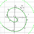
To begin with, magnetic saturation of the transformer core. That depends only on construction details, primary voltage, and frequency.
A transformer has primary current even with no load (zero secondary current).
It's called the magnetizing current, and is normally a small fraction of rated operating current.
Just enough to cyclically magnetize the core, so the induced voltage in primary winding (we could call it "back EMF") matches the applied voltage.
The induced voltage is limited by core saturation -- the point at which the core material can't be magnetized any more. If you apply more primary voltage (at the same frequency), the magnetizing current rapidly goes up to destructive levels.
from http://www.bookcracker.com/transformer/
If you took your 15 kV NST and tried to get 30 kV by connecting primary to 240 volts, you would immediately trip the 240 volt circuit breaker. The situation would be closer to a short circuit than to a mere overload.
If you connected the secondary of NST1 to the primary of NST2, things would be less dramatic. NST1 secondary current is self-limiting, and won't exceed the nameplate value (probably 20 or 30 mA). If that's less than the normal magnetizing current of NST2, then the second transformer will happily operate at _less_ than its rated voltage.
Exercise for Liam: measure the magnetizing current of your NST at normal voltage with no load. If you don't have a meter with an AC mA range, you can measure the AC voltage across a low-ohm sense resistor in series with the NST primary winding. Please tell us your face-to-face mentor is competent to help. For extra credit, see how the primary current changes when the secondary is shorted, or is lighting a luminous tube (e.g. unballasted fluorescent lamp), or a Jacob's Ladder.
A transformer has primary current even with no load (zero secondary current).
It's called the magnetizing current, and is normally a small fraction of rated operating current.
Just enough to cyclically magnetize the core, so the induced voltage in primary winding (we could call it "back EMF") matches the applied voltage.
The induced voltage is limited by core saturation -- the point at which the core material can't be magnetized any more. If you apply more primary voltage (at the same frequency), the magnetizing current rapidly goes up to destructive levels.
If you took your 15 kV NST and tried to get 30 kV by connecting primary to 240 volts, you would immediately trip the 240 volt circuit breaker. The situation would be closer to a short circuit than to a mere overload.
If you connected the secondary of NST1 to the primary of NST2, things would be less dramatic. NST1 secondary current is self-limiting, and won't exceed the nameplate value (probably 20 or 30 mA). If that's less than the normal magnetizing current of NST2, then the second transformer will happily operate at _less_ than its rated voltage.
Exercise for Liam: measure the magnetizing current of your NST at normal voltage with no load. If you don't have a meter with an AC mA range, you can measure the AC voltage across a low-ohm sense resistor in series with the NST primary winding. Please tell us your face-to-face mentor is competent to help. For extra credit, see how the primary current changes when the secondary is shorted, or is lighting a luminous tube (e.g. unballasted fluorescent lamp), or a Jacob's Ladder.
Last edited by Rich Feldman on Sun Dec 28, 2014 11:35 pm, edited 1 time in total.
All models are wrong; some models are useful. -- George Box
-
Liam David
- Posts: 527
- Joined: Sat Jan 25, 2014 5:30 pm
- Real name: Liam David
- Location: PPPL
Re: Attach NST Output to NST Input
Thank you Rich for your helpful explanation and the graph. If I were to increase the voltage, I would have to decrease the frequency in order to prevent saturating the core and drawing too many amps, right?
-
Rich Feldman
- Posts: 1471
- Joined: Mon Dec 21, 2009 6:59 pm
- Real name: Rich Feldman
- Location: Santa Clara County, CA, USA
Re: Attach NST Output to NST Input
Hi Liam.
Pay attention to Noah, who appears to speak from experience.
I have apparently been lucky never to break a working NST.
Can't say the same for ferroresonant CV transformer units.
To avoid saturation as you up the voltage, you would have to up the frequency.
The parameter being stressed is maximum magnetic flux swing in webers.
Same thing as the volt-second integral (per half cycle, per turn) in every winding around that flux.
"Switch Mode" transformers are run faster than 20 kHz, allowing whole volts per turn from small flux swings in ferrite cores.
As others have hinted, you can't increase the voltage by much without overstressing the high voltage insulation.
It's already potted in tar, so I don't see where oil immersion would help. I bet it would make a gooey mess.
All models are wrong; some models are useful. -- George Box
-
Charles Vorbach
- Posts: 45
- Joined: Tue Oct 14, 2014 6:39 pm
- Real name: Charles Vorbach
Re: Attach NST Output to NST Input
It's pretty easy to connect NST in parallel though to get more current and then possible to use a CW multiplier to get the voltage you need.
Here is a link showing how to phase NSTs:
http://youtu.be/KSlQjw9OPG4
Here is a link showing how to phase NSTs:
http://youtu.be/KSlQjw9OPG4
-
Richard Hull

- Moderator
- Posts: 15024
- Joined: Fri Jun 15, 2001 9:44 am
- Real name: Richard Hull
Re: Attach NST Output to NST Input
Get more current via parrallel connection? True! Voltage will forever be limited due to center taps, however. voltage multiplier effectiveness is related to capacitor stage values. Very large capacity needed to support stage effectiveness. It can be done, of course. Unfortunately, most here are not up to the task or have the money or supplies needed to make it happen. The issue usually rests with inexperience and lack of good reliable metering to know what you actually have at the output under load. Only the real go-getters stand much of a chance at this effort. When finished, if successful, they will have a very dangerous power source.
Richard Hull
Richard Hull
Progress may have been a good thing once, but it just went on too long. - Yogi Berra
Fusion is the energy of the future....and it always will be
The more complex the idea put forward by the poor amateur, the more likely it will never see embodiment
Fusion is the energy of the future....and it always will be
The more complex the idea put forward by the poor amateur, the more likely it will never see embodiment