Criticize my HV supply design
Posted: Fri Nov 10, 2017 10:03 am
This will be a long winded post, or perhaps even several posts, so bear with me as I go through this. I've posted this somewhere else already (but this won't be a literal copy/paste of the material from there, it's mostly re-written including some unchanged snippets). I've edited it quite a bit for posting here, eliminating irrelevant stuff, and adding new material as well.
NB as of 11/10/17 no HV has been generated from any of the designs below; currently the practical build is on hold until sometime next week due to other obligations.
Essentially it comes down to this: I have been unable to obtain anything suitable for a HV power supply for my fusor, so I decided to make my own from scratch. It's the only major subsystem for my fusor in which I haven't been able to make any progress with in years, including scrounging or buying major components. Notably the HV transformer of adequate voltage and power specs.
My aim is now to achieve a power supply that can deliver a minimum of 30kV at a minimum 30mA, power 900W or more. That's goal #1.
I was unsuccessful in finding an affordable power supply with the required parameters. While I am still looking, I've decided to make my own power supply. For efficiency, it will be a switched mode power supply (SMPS) with a ferrite core transformer.
All calculations below are for a frequency of the SMPS of 20kHz.
A quick back-of-the-napkin calculation gives me this for the requirements of the ferrite transformer. For a supported power of 900W, it would need a core area of at least 35cm^2. The power supported increases with the square of the core area.
Cores that I can find at reasonable prices online are EE140 type, which have a core area of 4x4=16cm^2. One of these supports about 180W power transfer. Not enough.
But if I stick 2 of them together in parallel that will give me a core area of 32cm^2, or a power of about 750W. Still not enough.
How about 3 cores? That is an area of 48cm^2, and maximum supported power of about 1700W. Check.
The material of these cores is a Mn-Zn ferrite, PC40. Datasheet gives for PC40:
-initial permeability 2300 at 23 degrees C
-Curie temperature above 200 degrees C
-saturation flux Bs of 0.5T at 23 degrees, or 0.38T at 100 degrees C; this is important.
I will assume that it will be pushed to its limits and calculate for max temperature of 100C.
From previous failures I have acquired the habit of over-engineering things. This not only gives me a safety factor, but also allows me to upgrade stuff in place if I need higher specs later. Some speculations later in this post regarding upgrades.
So I will multiply the Bs at 100C with a factor of 0.3 and use that for calculations as maximum flux.
That gives me a Bs of 0.38 * 0.3=0.114T, or 114mT or 1140gauss.
Calculations for primary winding.
B(gauss)=V*T(on)*10^8/2*Ae*N
V=primary voltage
T(on)=duty cycle divided by frequency
Ae=core area (cm^2)
N=number of turns
Or expressed otherwise
N/V (turns per volt)=T(on)*10^8/2*Ae*B
T(on)=0.5(square wave with 50% duty cycle)/20000Hz=0.25*10^-4
Ae=48cm^2
B=1140gauss
thus N/V=0.25*10^4/2*48*1140=0.25/10.944=0.0228 turns per volt
For the primary I will use mains AC (120V in the US), passed through a 2KW autotransformer for power control, rectified with a full-wave bridge and filtered, then switched on/off at 20kHz/50% duty cycle with power MOSFETs or IGBTs (probably a half-bridge configuration) into the primary.
120V is the Vrms of the mains; Vpeak is 169V (Vrms/0.707); Vaverage is 108V
I will aim for an average voltage of 12000V in the secondary, thus use the 108V value in the subsequent power calculations. The Vpeak in the secondary will be 18837V, and I will use this to select components tolerances. I won't calculate a transformer that gives me more than this for practical reasons (insulation etc), and will raise the voltage to the desired values using a Cockroft-Walton voltage multiplier in the secondary.
I will derive the current needed in the secondary from what the CW multiplier needs to achieve the desired output parameters.
For an input of 12000V, a 1-stage CW multiplier using 4nF capacitors at a frequency of 20kHz, in order to supply 30mA output will require at least 83mA input current. The output voltage will be 33kV with a ripple of 380V. That is acceptable.
Will round up required current to 100mA. This is what I will use in subsequent secondary calculations
(subsequent update and edit: I now have 10nF/30kV capacitors and if I use 2 in parallel for the stages that gives me 20nF capacity; plugging that in the CWM calculations I get for a 1-stage multiplier:
Iout=30mA, Iin=84mA, Vout=33.6kV, ripple=75V, total power 1005W. That is even better. Will use that)
Primary turns.
N/V=0.0228 (from above) V=108V (average), 168V(peak), Vrms=120
N=2.46 turns for average voltage, or 3.69 for peak. Round up to 4 turns.
Secondary turns.
Vavg=12000V, Vpeak=18837V. Turn ratio=12000/108 + 10%(compensate for losses)=111.11+11.11=122.22. Round up to 123
Turns=123*4=492.Check.
Secondary wire gauge.
The wire needs to carry 100mA at least, so a minimum of 31AWG, or 0.226mm diameter. That will take a current of up to 113mA. Check.
If I later would require the secondary to provide more current I could use 30AWG (up to 140mA) or AWG29 (up to 180mA). It would be pointless to increase the wire gauge above that, since at 180mA the power would be 2100W, which is more than the transformer core supports. AWG30 would support up to 1680W which is within core spec. Make a note to not exceed 140mA in the secondary.
(update: due to practical considerations will use 28AWG wire. Supports up to 230mA, much more than needed)
Primary wire gauge.
Current in primary: 100mA*123(turn ratio)=12.3A Will apply the same overengineering concept and round up to 15A minimum.
Wire size for 15A is 10AWG, or 2.58mm diameter.
But hold, at 20kHz there will be a skin effect. The skin depth at 20kHz is 0.5mm, so any wire over 1mm diameter will be affected by a reduction in its current carrying capacity. For 10AWG, this leaves a surface area equivalent of 21AWG (0.72mm diameter) which can only carry 1.2A. Not good enough.
Quick area calculations taking into effect the skin effect shows that I will need primary wire of at least 6.89mm diameter. 1AWG(7.34mm diameter) would be needed.
But hold again. Working with 7.5mm copper is going to be a nightmare, and wasteful of conductor area utilization. Better plan is to wind the primary with several strands of thinner wire in parallel, each carrying less current but the sum of the currents meeting my specs.
How about 12AWG wire? Diameter 2.05mm; the skin depth is 0.5mm so subtract 1mm (2*0.5) leaves 1.05mm unused in the core. That's equivalent to 18AWG which means I will derate the 12AWG current by a 18AWG current, thus 9.3A-2.3A=7A per strand at 20kHz. 2 strands in parallel would carry 14A which is close to 15.
How about 14AWG wire? applying the same calculations I need to derate it by the equivalent of a 22AWG due to the skin effect, thus 5.9A-0.92A=4.98A. A secondary wound with 3 of these in parallel would carry 3*4.98A=14.94A. I think I will chose this version which means the secondary will be 3*4turns 14AWG wire.
So overall I will need:
3*EE140 cores in parallel
3*4 turns of 14AWG wire primary wound over all 3 cores at once
492 turns of 31AWG wire (or better-28AWG chosen for practical reasons) wound over all 3 cores at once.
End transformer calculations.
Input: AC mains through autotransformer, full wave rectifier bridge, filtering capacitor (all specified for at least 200V, 15A); half-bridge MOSFET/IGBT plus driver at 20kHz.
Output: 1-stage CW multiplier, 33kV at 30mA.
Power required for output including CW losses: 1005W, approx 1kW.
Can later add a second CW stage for higher output. With the second stage, output would be 66kV/30mA with 530V ripple, but the secondary current would rise to 161mA and total power required rise to 2000W. That is out of spec.
However if I only require a current of 18mA the output will be 66.8kV with 315V ripple, and secondary current required 100mA for power of 1200W. That is within spec. So this upgrade in place would be viable without needing the transformer to be rewound. More voltage and more power=better fusion efficiency.
The maximum I could extract from this design with 2-stage CW multiplier, based on the 140mA limit for the secondary current set above, would be 25mA at 66.7kV with 440V ripple. That gives a power of 1669W.
The weight of the transformer, based on the weight of the cores plus that of the wire, is estimated at about 14kg. Size 14x14x12cm.
Please feel free to check my calculations and make appropriate corrections.
------------------------------------------------------------------------------------------------------------------------------------------------------------------------------
While I plan forward about a big power supply, I'm starting to build a small one, just about 2W of power (later revised to 40W, see below), for the specific purpose of testing my designs and components. I have a (large for other purposes, but small for a power transformer) ferrite toroid of unknown material (I think however that they are more or less an equivalent of FT290-43, http://toroids.info/FT290-43.php ) that I got a while ago from a Chinese seller; it's 76x38x10mm (ODxIDxh)
The front-end will run at 12V and will have a 20kHz square wave generator, a gate driver, a gate driver transformer that will provide out-of-phase gate signals to the 2 power MOSFETs/IGBTs that drive the transformer primary in half-bridge configuration. If that works well in small-scale (12V primary, 1000V secondary) then I can scale it up with the same drive circuit but bigger MOSFETs and power transformer.
This will allow me to test
a. my driver design
b. my skills at winding toroidal transformers, which I've done in the past but not to a great extent
c. components, especially MOSFETs, HV capacitors and diodes.
d. RF interference on my neutron detection system. A small HV arc set not far from the detection tube should provide ample amounts of that.
------------------------------------------------------------------------------------------------------------------------------------------------------------------------------
I have decided to use IGBTs instead of MOSFETS in the power driver. It won't change much in the other electronics part, but I expect to have smaller power losses in the driver stage, and thus less heat generated.
Why? A MOSFET is essentially a voltage-controlled resistor. Even when fully "on" it's still a resistor; a small one, but the voltage drop on it increases with the voltage it switches. An IGBT is essentially a BJT which gives it a Vcesat in the parameter list - essentially a fixed voltage drop which varies little with the switched voltage.
At low voltages, say 12V, the MOSFET is better. Say we have a MOSFET with Rds(on) of 100mOhms. That means it will drop 1.2V at 12V. IGBTs have a Vcesat on the order of 1.8-2.5V. So at 12V the
MOSFET will waste less power and generate less heat. But at 120V, the MOSFET will have a voltage drop of 12V, while the IGBT will still only dissipate 1.8V.
IGBTs are a little slower than MOSFETS, but that would only matter if I were using a switching frequency of 400kHz or more. Since I use 20kHz that won't matter.
I found in my electronics stash some 600V/60A IGBTs left from a previous project, and will use those. If needed, I have a few 1200V IGBTs on order which I expect to get in a couple of weeks.
------------------------------------------------------------------------------------------------------------------------------------------------------------------------------
So I sat down and spent my Sunday by winding a transformer. I'm testing the "stacked cores" hypothesis. The medium ferrite toroids that I have, if used individually should support 2.5W, but if stacked by 4 would reach 40W or so. If this tests good I can scale up to the stacked extra-large EE cores.
Here are pictures (pics 1,2,3). Testing another day, I'm too tired today. This business took me 2 hours at least. It reminded me how much I hate winding toroids. I had avoided doing it for 20+ years until today.
Anyway, specs are as follows.
4xtoroid (cheap, unknown parameters from China), 76mm OD, 38mm ID, 13mm height
secondary: 170 turns 28AWG wire (I didn't need to use 28AWG, 35AWG would have been enough but it would have been technically more difficult); hopefully will give around 1000V, 40mA.
primary: 2 turns, 2 strands 18AWG wire; operating at 12V, 20kHz, 3.25A if the power rating is correct
Need to build an appropriate driver.
As far as the generator/driver goes, I don't need any advanced PWM features, just a fixed frequency oscillator, an intermediate amplifier/gate driver and the half bridge itself. A 555, a few transistors, a small gate transformer and the IGBTs are all I need beside the large transformer itself. And if I calculate everything right I can build it once, and use both with the test transformer above and with the final transformer.
------------------------------------------------------------------------------------------------------------------------------------------------------------------------------
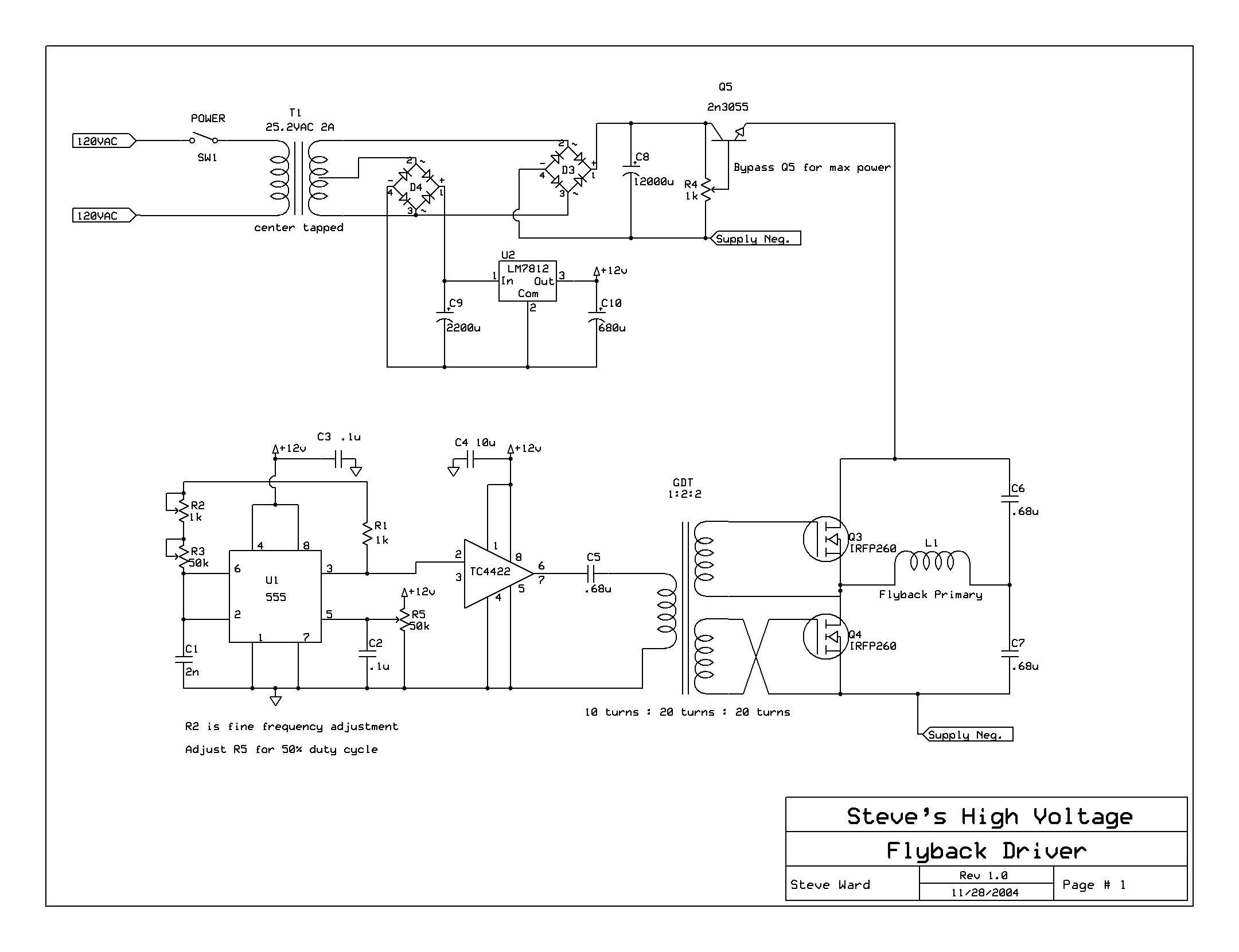
Here's a quick and dirty schematic (pic5). It's not original, I lifted a large part of it from http://www.stevehv.4hv.org/FBD/FBschematic.JPG (but even that isn't really original, it's a classic 555 oscillator with 50% duty cycle, an integrated driver which I replaced with a couple transistors, and a classic half bridge). The component values are based on what I found in my boxes and could be replaced with anything equivalent or better. The gate drive transformer should be wound with at least 24AWG wire to allow for currents up to 500mA. One of the secondaries is wound in the opposite direction compared to the primary and the other secondary. Pic4 is the gate transformer finished.
I didn't add over-current protection, but that could go like this: small current-sensing transformer in series with the big transformer primary in the bridge; secondary from this would be rectified and fed into a comparator, then the comparator output into an optocoupler; the optocoupler output is used to reduce the drive in the driver, e.g. by switching different resistors instead of the one in the base of the second transistor. This resistor (which I marked 100-1k) is what determines the strength of the gate drive. It should be determined experimentally, and will depend on the power components in the bridge and their gate drive requirements.
Or even better, a small signal MOSFET such as BS170 connected between the base of the first transistor and the ground could do the job; perhaps even working as an AGC/voltage-controlled resistor to reduce drive signal if output exceeds a certain limit.
The IRF640 should be good enough for operating the power section at 12V; but for 120V either higher-rated MOSFETs or the IGBTs noted will be necessary.
-----------------------------------------------------------------------------------------------------------------------------------------------------------------------
AGC /overcurrent protection idea. (pic6)
For a modular build, everything from the 555 up to and including the gate transformer, and the optocoupler would be in one module (the signal module); everything downstream and including the power MOSFETs, and the current sensing circuitry would be in the power module. The current sensing part would be dimensioned to the power transformer and voltage in use, and would provide the same signal to the OC. I could then switch power modules depending on the transformer I use and keep the same low-signal part.
--------------------------------------------------------------------------------------------------------------------------------------------------------------------------
Let's discuss the secondary of the final large core EE transformer. I actually have a question (or several) for the collective mind of this board at the end.
Per calculations above I will need 492 turns of 30AWG or heavier wire. I have been shopping around, and high-voltage-rated 30AWG wire is hard to find in appropriate lengths (200m is what I need) not to mention fairly expensive even from the usual Chinese sources. I was able to find some 28AWG wire in 300m lengths that's fairly affordable (thus the updates in earlier parts of this post with 28AWG used). The catch is that it's rated for 3000V not 10000 or 20000 as I was hoping. I will come back to that.
Now assuming that I use this wire, based on the number of turns, the physical properties of the wire and the space I have available in the core window, the most reasonable geometry would be to wind it in layers of 41 turns per layer, 12 layers total. 41*12=492.
The voltage in the secondary will be 12000Vrms. That comes to 1000V per layer. That would mean the rated voltage résistance of the wire isn't reached unless you consider the difference of potential across 3 layers deep (e.g. from the 1st layer to the 4th layer). Even when considering the peak voltage of around 19000V you still have to look across 2 layers deep (1st layer to 3rd layer etc).
Would this be safe? What if I use some extra insulation between layers, say some thin polypropylene/PVC or silicone film? What if I encase the whole secondary in silicone or epoxy resin?
Also, what if I submerge the transformer in mineral oil as it's usually done with HV transformers? Actually I have some reservations regarding that. The wire insulation is silicone. I don't know if this silicone is resistant to mineral oil, or if its mechanical and/or electrical properties wouldn't be degraded by the oil.
As always I appreciate your opinions.
------------------------------------------------------------------------------------------------------------------------------------------------------------------------------
That's all she wrote for now.
I know we have HV experts on this board. Please point any flaws in the plan above. Better I find out now than later.
Above has been proof-read twice, but if any spelling errors are still left please use your imagination to correct.
NB as of 11/10/17 no HV has been generated from any of the designs below; currently the practical build is on hold until sometime next week due to other obligations.
Essentially it comes down to this: I have been unable to obtain anything suitable for a HV power supply for my fusor, so I decided to make my own from scratch. It's the only major subsystem for my fusor in which I haven't been able to make any progress with in years, including scrounging or buying major components. Notably the HV transformer of adequate voltage and power specs.
My aim is now to achieve a power supply that can deliver a minimum of 30kV at a minimum 30mA, power 900W or more. That's goal #1.
I was unsuccessful in finding an affordable power supply with the required parameters. While I am still looking, I've decided to make my own power supply. For efficiency, it will be a switched mode power supply (SMPS) with a ferrite core transformer.
All calculations below are for a frequency of the SMPS of 20kHz.
A quick back-of-the-napkin calculation gives me this for the requirements of the ferrite transformer. For a supported power of 900W, it would need a core area of at least 35cm^2. The power supported increases with the square of the core area.
Cores that I can find at reasonable prices online are EE140 type, which have a core area of 4x4=16cm^2. One of these supports about 180W power transfer. Not enough.
But if I stick 2 of them together in parallel that will give me a core area of 32cm^2, or a power of about 750W. Still not enough.
How about 3 cores? That is an area of 48cm^2, and maximum supported power of about 1700W. Check.
The material of these cores is a Mn-Zn ferrite, PC40. Datasheet gives for PC40:
-initial permeability 2300 at 23 degrees C
-Curie temperature above 200 degrees C
-saturation flux Bs of 0.5T at 23 degrees, or 0.38T at 100 degrees C; this is important.
I will assume that it will be pushed to its limits and calculate for max temperature of 100C.
From previous failures I have acquired the habit of over-engineering things. This not only gives me a safety factor, but also allows me to upgrade stuff in place if I need higher specs later. Some speculations later in this post regarding upgrades.
So I will multiply the Bs at 100C with a factor of 0.3 and use that for calculations as maximum flux.
That gives me a Bs of 0.38 * 0.3=0.114T, or 114mT or 1140gauss.
Calculations for primary winding.
B(gauss)=V*T(on)*10^8/2*Ae*N
V=primary voltage
T(on)=duty cycle divided by frequency
Ae=core area (cm^2)
N=number of turns
Or expressed otherwise
N/V (turns per volt)=T(on)*10^8/2*Ae*B
T(on)=0.5(square wave with 50% duty cycle)/20000Hz=0.25*10^-4
Ae=48cm^2
B=1140gauss
thus N/V=0.25*10^4/2*48*1140=0.25/10.944=0.0228 turns per volt
For the primary I will use mains AC (120V in the US), passed through a 2KW autotransformer for power control, rectified with a full-wave bridge and filtered, then switched on/off at 20kHz/50% duty cycle with power MOSFETs or IGBTs (probably a half-bridge configuration) into the primary.
120V is the Vrms of the mains; Vpeak is 169V (Vrms/0.707); Vaverage is 108V
I will aim for an average voltage of 12000V in the secondary, thus use the 108V value in the subsequent power calculations. The Vpeak in the secondary will be 18837V, and I will use this to select components tolerances. I won't calculate a transformer that gives me more than this for practical reasons (insulation etc), and will raise the voltage to the desired values using a Cockroft-Walton voltage multiplier in the secondary.
I will derive the current needed in the secondary from what the CW multiplier needs to achieve the desired output parameters.
For an input of 12000V, a 1-stage CW multiplier using 4nF capacitors at a frequency of 20kHz, in order to supply 30mA output will require at least 83mA input current. The output voltage will be 33kV with a ripple of 380V. That is acceptable.
Will round up required current to 100mA. This is what I will use in subsequent secondary calculations
(subsequent update and edit: I now have 10nF/30kV capacitors and if I use 2 in parallel for the stages that gives me 20nF capacity; plugging that in the CWM calculations I get for a 1-stage multiplier:
Iout=30mA, Iin=84mA, Vout=33.6kV, ripple=75V, total power 1005W. That is even better. Will use that)
Primary turns.
N/V=0.0228 (from above) V=108V (average), 168V(peak), Vrms=120
N=2.46 turns for average voltage, or 3.69 for peak. Round up to 4 turns.
Secondary turns.
Vavg=12000V, Vpeak=18837V. Turn ratio=12000/108 + 10%(compensate for losses)=111.11+11.11=122.22. Round up to 123
Turns=123*4=492.Check.
Secondary wire gauge.
The wire needs to carry 100mA at least, so a minimum of 31AWG, or 0.226mm diameter. That will take a current of up to 113mA. Check.
If I later would require the secondary to provide more current I could use 30AWG (up to 140mA) or AWG29 (up to 180mA). It would be pointless to increase the wire gauge above that, since at 180mA the power would be 2100W, which is more than the transformer core supports. AWG30 would support up to 1680W which is within core spec. Make a note to not exceed 140mA in the secondary.
(update: due to practical considerations will use 28AWG wire. Supports up to 230mA, much more than needed)
Primary wire gauge.
Current in primary: 100mA*123(turn ratio)=12.3A Will apply the same overengineering concept and round up to 15A minimum.
Wire size for 15A is 10AWG, or 2.58mm diameter.
But hold, at 20kHz there will be a skin effect. The skin depth at 20kHz is 0.5mm, so any wire over 1mm diameter will be affected by a reduction in its current carrying capacity. For 10AWG, this leaves a surface area equivalent of 21AWG (0.72mm diameter) which can only carry 1.2A. Not good enough.
Quick area calculations taking into effect the skin effect shows that I will need primary wire of at least 6.89mm diameter. 1AWG(7.34mm diameter) would be needed.
But hold again. Working with 7.5mm copper is going to be a nightmare, and wasteful of conductor area utilization. Better plan is to wind the primary with several strands of thinner wire in parallel, each carrying less current but the sum of the currents meeting my specs.
How about 12AWG wire? Diameter 2.05mm; the skin depth is 0.5mm so subtract 1mm (2*0.5) leaves 1.05mm unused in the core. That's equivalent to 18AWG which means I will derate the 12AWG current by a 18AWG current, thus 9.3A-2.3A=7A per strand at 20kHz. 2 strands in parallel would carry 14A which is close to 15.
How about 14AWG wire? applying the same calculations I need to derate it by the equivalent of a 22AWG due to the skin effect, thus 5.9A-0.92A=4.98A. A secondary wound with 3 of these in parallel would carry 3*4.98A=14.94A. I think I will chose this version which means the secondary will be 3*4turns 14AWG wire.
So overall I will need:
3*EE140 cores in parallel
3*4 turns of 14AWG wire primary wound over all 3 cores at once
492 turns of 31AWG wire (or better-28AWG chosen for practical reasons) wound over all 3 cores at once.
End transformer calculations.
Input: AC mains through autotransformer, full wave rectifier bridge, filtering capacitor (all specified for at least 200V, 15A); half-bridge MOSFET/IGBT plus driver at 20kHz.
Output: 1-stage CW multiplier, 33kV at 30mA.
Power required for output including CW losses: 1005W, approx 1kW.
Can later add a second CW stage for higher output. With the second stage, output would be 66kV/30mA with 530V ripple, but the secondary current would rise to 161mA and total power required rise to 2000W. That is out of spec.
However if I only require a current of 18mA the output will be 66.8kV with 315V ripple, and secondary current required 100mA for power of 1200W. That is within spec. So this upgrade in place would be viable without needing the transformer to be rewound. More voltage and more power=better fusion efficiency.
The maximum I could extract from this design with 2-stage CW multiplier, based on the 140mA limit for the secondary current set above, would be 25mA at 66.7kV with 440V ripple. That gives a power of 1669W.
The weight of the transformer, based on the weight of the cores plus that of the wire, is estimated at about 14kg. Size 14x14x12cm.
Please feel free to check my calculations and make appropriate corrections.
------------------------------------------------------------------------------------------------------------------------------------------------------------------------------
While I plan forward about a big power supply, I'm starting to build a small one, just about 2W of power (later revised to 40W, see below), for the specific purpose of testing my designs and components. I have a (large for other purposes, but small for a power transformer) ferrite toroid of unknown material (I think however that they are more or less an equivalent of FT290-43, http://toroids.info/FT290-43.php ) that I got a while ago from a Chinese seller; it's 76x38x10mm (ODxIDxh)
The front-end will run at 12V and will have a 20kHz square wave generator, a gate driver, a gate driver transformer that will provide out-of-phase gate signals to the 2 power MOSFETs/IGBTs that drive the transformer primary in half-bridge configuration. If that works well in small-scale (12V primary, 1000V secondary) then I can scale it up with the same drive circuit but bigger MOSFETs and power transformer.
This will allow me to test
a. my driver design
b. my skills at winding toroidal transformers, which I've done in the past but not to a great extent
c. components, especially MOSFETs, HV capacitors and diodes.
d. RF interference on my neutron detection system. A small HV arc set not far from the detection tube should provide ample amounts of that.
------------------------------------------------------------------------------------------------------------------------------------------------------------------------------
I have decided to use IGBTs instead of MOSFETS in the power driver. It won't change much in the other electronics part, but I expect to have smaller power losses in the driver stage, and thus less heat generated.
Why? A MOSFET is essentially a voltage-controlled resistor. Even when fully "on" it's still a resistor; a small one, but the voltage drop on it increases with the voltage it switches. An IGBT is essentially a BJT which gives it a Vcesat in the parameter list - essentially a fixed voltage drop which varies little with the switched voltage.
At low voltages, say 12V, the MOSFET is better. Say we have a MOSFET with Rds(on) of 100mOhms. That means it will drop 1.2V at 12V. IGBTs have a Vcesat on the order of 1.8-2.5V. So at 12V the
MOSFET will waste less power and generate less heat. But at 120V, the MOSFET will have a voltage drop of 12V, while the IGBT will still only dissipate 1.8V.
IGBTs are a little slower than MOSFETS, but that would only matter if I were using a switching frequency of 400kHz or more. Since I use 20kHz that won't matter.
I found in my electronics stash some 600V/60A IGBTs left from a previous project, and will use those. If needed, I have a few 1200V IGBTs on order which I expect to get in a couple of weeks.
------------------------------------------------------------------------------------------------------------------------------------------------------------------------------
So I sat down and spent my Sunday by winding a transformer. I'm testing the "stacked cores" hypothesis. The medium ferrite toroids that I have, if used individually should support 2.5W, but if stacked by 4 would reach 40W or so. If this tests good I can scale up to the stacked extra-large EE cores.
Here are pictures (pics 1,2,3). Testing another day, I'm too tired today. This business took me 2 hours at least. It reminded me how much I hate winding toroids. I had avoided doing it for 20+ years until today.
Anyway, specs are as follows.
4xtoroid (cheap, unknown parameters from China), 76mm OD, 38mm ID, 13mm height
secondary: 170 turns 28AWG wire (I didn't need to use 28AWG, 35AWG would have been enough but it would have been technically more difficult); hopefully will give around 1000V, 40mA.
primary: 2 turns, 2 strands 18AWG wire; operating at 12V, 20kHz, 3.25A if the power rating is correct
Need to build an appropriate driver.
As far as the generator/driver goes, I don't need any advanced PWM features, just a fixed frequency oscillator, an intermediate amplifier/gate driver and the half bridge itself. A 555, a few transistors, a small gate transformer and the IGBTs are all I need beside the large transformer itself. And if I calculate everything right I can build it once, and use both with the test transformer above and with the final transformer.
------------------------------------------------------------------------------------------------------------------------------------------------------------------------------
Here's a quick and dirty schematic (pic5). It's not original, I lifted a large part of it from http://www.stevehv.4hv.org/FBD/FBschematic.JPG (but even that isn't really original, it's a classic 555 oscillator with 50% duty cycle, an integrated driver which I replaced with a couple transistors, and a classic half bridge). The component values are based on what I found in my boxes and could be replaced with anything equivalent or better. The gate drive transformer should be wound with at least 24AWG wire to allow for currents up to 500mA. One of the secondaries is wound in the opposite direction compared to the primary and the other secondary. Pic4 is the gate transformer finished.
I didn't add over-current protection, but that could go like this: small current-sensing transformer in series with the big transformer primary in the bridge; secondary from this would be rectified and fed into a comparator, then the comparator output into an optocoupler; the optocoupler output is used to reduce the drive in the driver, e.g. by switching different resistors instead of the one in the base of the second transistor. This resistor (which I marked 100-1k) is what determines the strength of the gate drive. It should be determined experimentally, and will depend on the power components in the bridge and their gate drive requirements.
Or even better, a small signal MOSFET such as BS170 connected between the base of the first transistor and the ground could do the job; perhaps even working as an AGC/voltage-controlled resistor to reduce drive signal if output exceeds a certain limit.
The IRF640 should be good enough for operating the power section at 12V; but for 120V either higher-rated MOSFETs or the IGBTs noted will be necessary.
-----------------------------------------------------------------------------------------------------------------------------------------------------------------------
AGC /overcurrent protection idea. (pic6)
For a modular build, everything from the 555 up to and including the gate transformer, and the optocoupler would be in one module (the signal module); everything downstream and including the power MOSFETs, and the current sensing circuitry would be in the power module. The current sensing part would be dimensioned to the power transformer and voltage in use, and would provide the same signal to the OC. I could then switch power modules depending on the transformer I use and keep the same low-signal part.
--------------------------------------------------------------------------------------------------------------------------------------------------------------------------
Let's discuss the secondary of the final large core EE transformer. I actually have a question (or several) for the collective mind of this board at the end.
Per calculations above I will need 492 turns of 30AWG or heavier wire. I have been shopping around, and high-voltage-rated 30AWG wire is hard to find in appropriate lengths (200m is what I need) not to mention fairly expensive even from the usual Chinese sources. I was able to find some 28AWG wire in 300m lengths that's fairly affordable (thus the updates in earlier parts of this post with 28AWG used). The catch is that it's rated for 3000V not 10000 or 20000 as I was hoping. I will come back to that.
Now assuming that I use this wire, based on the number of turns, the physical properties of the wire and the space I have available in the core window, the most reasonable geometry would be to wind it in layers of 41 turns per layer, 12 layers total. 41*12=492.
The voltage in the secondary will be 12000Vrms. That comes to 1000V per layer. That would mean the rated voltage résistance of the wire isn't reached unless you consider the difference of potential across 3 layers deep (e.g. from the 1st layer to the 4th layer). Even when considering the peak voltage of around 19000V you still have to look across 2 layers deep (1st layer to 3rd layer etc).
Would this be safe? What if I use some extra insulation between layers, say some thin polypropylene/PVC or silicone film? What if I encase the whole secondary in silicone or epoxy resin?
Also, what if I submerge the transformer in mineral oil as it's usually done with HV transformers? Actually I have some reservations regarding that. The wire insulation is silicone. I don't know if this silicone is resistant to mineral oil, or if its mechanical and/or electrical properties wouldn't be degraded by the oil.
As always I appreciate your opinions.
------------------------------------------------------------------------------------------------------------------------------------------------------------------------------
That's all she wrote for now.
I know we have HV experts on this board. Please point any flaws in the plan above. Better I find out now than later.
Above has been proof-read twice, but if any spelling errors are still left please use your imagination to correct.