DIY Turbopump Controller
-
Nikodem Czechowski
- Posts: 13
- Joined: Sat Jan 16, 2021 3:56 pm
- Real name: Nikodem Czechowski
- Location: Poland
- Contact:
Re: DIY Turbopump Controller
OK Nicolas  If you would need any assistance with PCB and electronics, feel free to ask.
-
Jerry Biehler
- Posts: 975
- Joined: Tue Nov 24, 2009 3:08 am
- Real name:
- Location: Beaverton, OR
Re: DIY Turbopump Controller
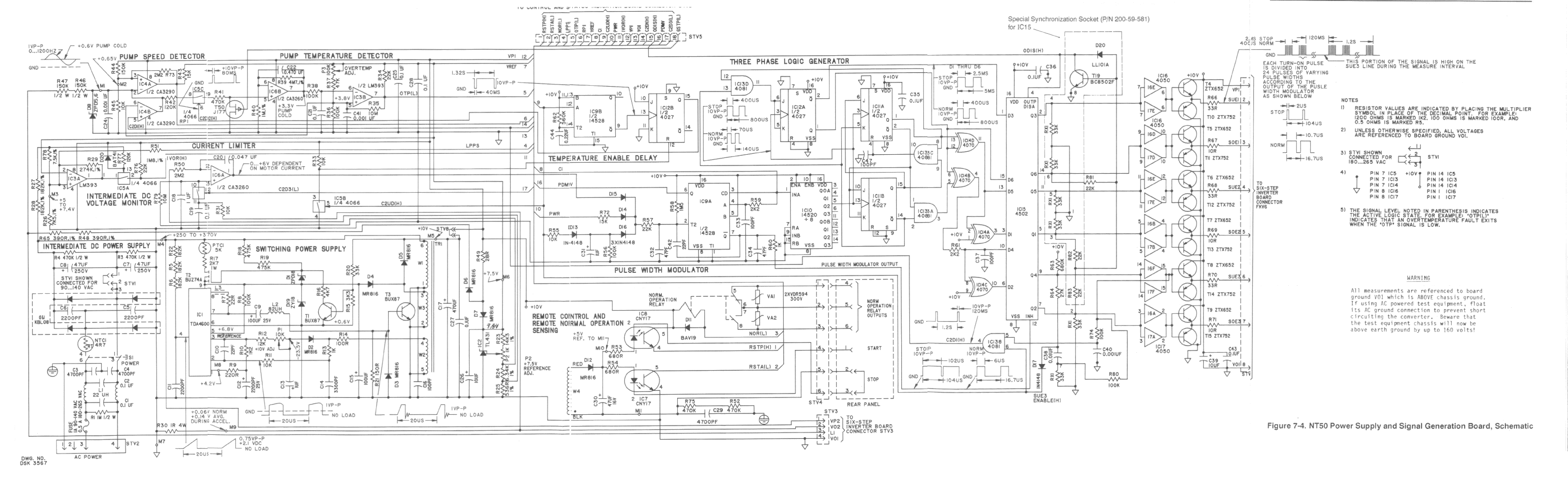
I have an official schematic for the controller for these pumps. https://drive.google.com/file/d/0B1bUBQ ... sp=sharing
There are about 4 drive models that will run this pump, the NT10, NT12, and NT13 as well as the NT50 which I have provided the schematic for. Sometimes these models do pop on ebay at reasonable prices. I also may know someone with working NT50s for sale. I think there is a NT11 but I have never seen one.
There are about 4 drive models that will run this pump, the NT10, NT12, and NT13 as well as the NT50 which I have provided the schematic for. Sometimes these models do pop on ebay at reasonable prices. I also may know someone with working NT50s for sale. I think there is a NT11 but I have never seen one.
-
Nikodem Czechowski
- Posts: 13
- Joined: Sat Jan 16, 2021 3:56 pm
- Real name: Nikodem Czechowski
- Location: Poland
- Contact:
Re: DIY Turbopump Controller
NT50 seems to be overly complicated and based on discrete ICs and logic - a thing, that easily can fit into an Arduino module. I would not recomend replicating it nowadays. Maybe the driver stage, of the transistors are still available.Jerry Biehler wrote: ↑Sun Jan 24, 2021 5:49 am I have an official schematic for the controller for these pumps. https://drive.google.com/file/d/0B1bUBQ ... sp=sharing
There are about 4 drive models that will run this pump, the NT10, NT12, and NT13 as well as the NT50 which I have provided the schematic for. Sometimes these models do pop on ebay at reasonable prices. I also may know someone with working NT50s for sale. I think there is a NT11 but I have never seen one.
Also - what is a reasonable price for this controllers?
-
Richard Hull

- Moderator
- Posts: 15028
- Joined: Fri Jun 15, 2001 9:44 am
- Real name: Richard Hull
Re: DIY Turbopump Controller
Nikodem, please do not include quotes from the same thread. We are following it just fine. We have to tell this to many people who come here. I realize they are the norm on many sites. However, we are capable of fully and properly following a single post thread through all of its reply postings. Just simply reply without quoting something that is either immediately above or even 5 posts back in the thread, we will know what you are talking about in reply.
Richard Hull
Richard Hull
Progress may have been a good thing once, but it just went on too long. - Yogi Berra
Fusion is the energy of the future....and it always will be
The more complex the idea put forward by the poor amateur, the more likely it will never see embodiment
Fusion is the energy of the future....and it always will be
The more complex the idea put forward by the poor amateur, the more likely it will never see embodiment
-
Nicolas Krause

- Posts: 230
- Joined: Fri Sep 30, 2016 7:36 pm
- Real name: Nicolas Krause
- Location: Canada
- Contact:
Re: DIY Turbopump Controller
Thank you Jerry, that's sure to prove useful! As far as prices for a controller on eBay, my pump was 100$ w/out a controller, I routinely see Turbotroniks listed for over $1000, and unfortunately haven't had any look looking for cheap ones.
-
Rex Allers
- Posts: 574
- Joined: Sun Dec 30, 2012 3:39 am
- Real name:
- Location: San Jose CA
Re: DIY Turbopump Controller
Jerry,
I guess you posted the scans of the NT50 controller a few years back as I have a saved copy. (Not sure if the post was here or Coulter.) Anyway, I took your separate page scans and merged the ones that make up just the schematic in to one single big PNG file. There are other pages in your scans that have info besides the schematic so my pic isn't all of it.
I have just uploaded it here:
http://www.xertech.net/pub/NT-50_joined_1.png
Feel free to copy it and add to your page if you desire.
The size is actually smaller than your single page scans. I reduced the pixel dimensions to 1200 vertical and applied contrast to make more black and white. I think it is still quite readable in my version.
Rex Allers
-
Peter Schmelcher
- Posts: 228
- Joined: Sat Nov 13, 2010 1:56 am
- Real name: Peter Schmelcher
Re: DIY Turbopump Controller
Jerry thanks for the NT50 schematic and Rex for combining the sheets, both are downloaded for a future traumatic rainy day.
The information provides lots of clues for trouble shooting my similar NT10.
For the younger fellows, reverse engineering a black box is a miserable repair procedure and even if successful you still can’t be certain that the repair is behind you until you have lots of miles on the repair.
-Peter
The information provides lots of clues for trouble shooting my similar NT10.
For the younger fellows, reverse engineering a black box is a miserable repair procedure and even if successful you still can’t be certain that the repair is behind you until you have lots of miles on the repair.
-Peter
-
Nicolas Krause
- Posts: 230
- Joined: Fri Sep 30, 2016 7:36 pm
- Real name: Nicolas Krause
- Location: Canada
- Contact:
Re: DIY Turbopump Controller
I've hooked in the microcontroller, LCD, and on/off switch on the current schematic. Still lots of details left to verify though. I can't seem to attach the file to the message board but if you PM me I'll happily provide the file to any interested parties. I do have a question about the connectors to the transformers though, I'm not 100% sure on their use. I don't think they're necessary to hook into the microcontroller but I could be wrong?
-
ArkadiuszGibes
- Posts: 8
- Joined: Wed Jan 08, 2020 8:28 am
- Real name: Arkadiusz
Re: DIY Turbopump Controller
Hi guys
I already made driver for Turbovac 50. You can see it here https://www.youtube.com/watch?v=HPkOAWe2w2c - it's part of my rotor balancing "toy" now.
The project is based on https://github.com/NiklasFauth/stm32-turbotronik - it's not mine. I did some changes to it and it works well. If someone would like i can shere PCBs and schematic. There is also DC/DC (mains/200V) converter that i made for this pump, but it requires to wind the transformer and the one that i used was just some old crap which i took out from old TV. I will try to prepare some more detailed description soon. Im at work now .
Best Regards
Arek
-
Nikodem Czechowski
- Posts: 13
- Joined: Sat Jan 16, 2021 3:56 pm
- Real name: Nikodem Czechowski
- Location: Poland
- Contact:
Re: DIY Turbopump Controller
Hi Arek!
Please do share your schematic and PCB. I thinks this is what I'm looking for for my TMP
Please do share your schematic and PCB. I thinks this is what I'm looking for for my TMP
-
ArkadiuszGibes
- Posts: 8
- Joined: Wed Jan 08, 2020 8:28 am
- Real name: Arkadiusz
Re: DIY Turbopump Controller
Hi
Here is a repository with kicad files: https://gitlab.com/arkadiusz.g/turbotronik1.0hw/
However, that was the first version of this driver, so it has some issues. One of them is LDO regulator, there is to much current that goes trough it and it is getting hot quite fast. I replaced it with Chinese dc/dc reg and it's fine - this is not updated in those pcb files.
This is a dc/dc converter that i used - https://allegro.pl/oferta/modul-przetwo ... 7563986495,
Also, as i built in on top of someones else code, it is using lcd that is driven by i2c -> parallel IC. From what iv'e seen, sometimes it was crashing so I had to repleace it with other type of lcd in my case.
Would be nice to update those files with DC/DC instead of LDO, and rebuild it with standard parallel interface for LCD so it could be used with cheap 2x16 displays. I can do this in free time, but feel free to do any modification you like.
Nikodem, I see that you are from Poland, if we would fix those "bugs" somehow then we could send it to production to china, and share some costs for pcbs.
-
Nikodem Czechowski
- Posts: 13
- Joined: Sat Jan 16, 2021 3:56 pm
- Real name: Nikodem Czechowski
- Location: Poland
- Contact:
Re: DIY Turbopump Controller
I will download the files tommorow and try to do the updates you have mentioned.
What pump you would want to drive it?
We can share the costs, I would ever need 10 pcbs for that - PM me and we can discuss the details.
What pump you would want to drive it?
We can share the costs, I would ever need 10 pcbs for that - PM me and we can discuss the details.
-
ArkadiuszGibes
- Posts: 8
- Joined: Wed Jan 08, 2020 8:28 am
- Real name: Arkadiusz
Re: DIY Turbopump Controller
Right now im playing with turbovac 50 pump, but it's damaged and i ordered turbovac360V. I will need to do some changes because TMP 360V works on lower voltage and frequency, but this is in most stuff that can be done by FW modifications. I will also repleace my 200V dc/dc converter to toroid transformer. Please shere the files when you update them.
Thanks
Thanks
-
Nicolas Krause
- Posts: 230
- Joined: Fri Sep 30, 2016 7:36 pm
- Real name: Nicolas Krause
- Location: Canada
- Contact:
Re: DIY Turbopump Controller
Hi Akradiusz, thanks for the links and files. If I could ask you to introduce yourself on the welcome forum it'd be a big help. The rules the old timers have setup here really help to preserve the quality of information on the forum!
-
ArkadiuszGibes
- Posts: 8
- Joined: Wed Jan 08, 2020 8:28 am
- Real name: Arkadiusz
Re: DIY Turbopump Controller
I already did it.
-
Nicolas Krause
- Posts: 230
- Joined: Fri Sep 30, 2016 7:36 pm
- Real name: Nicolas Krause
- Location: Canada
- Contact:
Re: DIY Turbopump Controller
Oh geez, I'm super sorry, missed that!
-
John Futter
- Posts: 1850
- Joined: Wed Apr 21, 2004 10:29 pm
- Real name: John Futter
- Contact:
Re: DIY Turbopump Controller
Nicolas
I have looked at your circuit
I did not use a micro directly to generate the drive frequency due to the danger of a reset or port hang from it.
There is a huge amount of stored energy in a turbo that is why in my diagram it was driven from the 4046 being used as a voltage controlled oscillator through a low pass filter that delayed abrupt voltage changes to the 4046. This filter should be changed to suit differing turbos ie longer time constant for 150 and 360 model pumps. Of coarse you change the buss rail voltage to suit these bigger pumps ie 14 / 28 volts for the tmp 360 and higher current mosfets and dont forget to lower the zener voltage in the buss protector
Fusor use includes high voltage power supplies and there will be the odd high voltage flashover that may reset your micro.
I certainly would not direct drive from a micro a larger turbo than the tmp50 due to the stored energy being released.
Even our turbo controllers have had the PSOC reset and the pump scream to a stop ( that what the big mosfet is for across the DC buss so that the electronics is saved from overvoltage from the motor back emf
-
Nicolas Krause
- Posts: 230
- Joined: Fri Sep 30, 2016 7:36 pm
- Real name: Nicolas Krause
- Location: Canada
- Contact:
Re: DIY Turbopump Controller
Thanks for the clarification John, I think I've misunderstood something fundamental about the operation of the circuit. I'm going to have to digest your post and look over things.
-
John Futter
- Posts: 1850
- Joined: Wed Apr 21, 2004 10:29 pm
- Real name: John Futter
- Contact:
Re: DIY Turbopump Controller
You are doing alright I'm just giving a bit of sage advice learnt from doing wrong it in the first place
ask away and i'll answer
ask away and i'll answer
-
Nicolas Krause
- Posts: 230
- Joined: Fri Sep 30, 2016 7:36 pm
- Real name: Nicolas Krause
- Location: Canada
- Contact:
Re: DIY Turbopump Controller
Hi John
I have a TMP 50 so I'm dealing with one of the smaller pumps. But my general understanding of the circuit is that you use some discrete logic to generate the signals which drive the half bridge connected to the 3-phase motor of the pump. I had assumed that hooking up the microcontroller to the logic chips you'd used would have provided enough of an innate buffer to prevent damage to the microcontroller. Looking at my circuit again and your comments I assume the problem is with the current measurement portion of the circuit correct? I expose the microcontroller to large changes in voltage/current at that point. If I included some sort of opto-isolation on that connection would I avoid the problem? I've never used opto-isolation in a current sensing application before.
I have a TMP 50 so I'm dealing with one of the smaller pumps. But my general understanding of the circuit is that you use some discrete logic to generate the signals which drive the half bridge connected to the 3-phase motor of the pump. I had assumed that hooking up the microcontroller to the logic chips you'd used would have provided enough of an innate buffer to prevent damage to the microcontroller. Looking at my circuit again and your comments I assume the problem is with the current measurement portion of the circuit correct? I expose the microcontroller to large changes in voltage/current at that point. If I included some sort of opto-isolation on that connection would I avoid the problem? I've never used opto-isolation in a current sensing application before.
-
John Futter
- Posts: 1850
- Joined: Wed Apr 21, 2004 10:29 pm
- Real name: John Futter
- Contact:
Re: DIY Turbopump Controller
Nicolas
It is hard to use linear optos to get volt and current sense across I make sure that there is series impedance then 5 volt TVS diodes across micro I/O pins
my comments were directed at some of the other posts where micro derived drive signals are use to drive the half bridge directly
a TMP 50 has about the same energy as a .22 LR cartridge where as a TMP150 is more like a .308 cartridge amount of stored energy
-
Nicolas Krause
- Posts: 230
- Joined: Fri Sep 30, 2016 7:36 pm
- Real name: Nicolas Krause
- Location: Canada
- Contact:
Re: DIY Turbopump Controller
Thanks for the clarification John, I've added the suggested circuit protection, now I just have to spec everything and layout the board! That's a nice way of thinking about energy as cartridge size, it's been awhile since I've been on a range but even though .22 LR is small I wouldn't want to be hit by either.
-
Michal Dvoracek
- Posts: 7
- Joined: Tue Jan 02, 2018 3:29 am
- Real name: Michal Dvoracek
- Location: Czech Republic
Re: DIY Turbopump Controller
Hello,
I'm finally built up my turbo controller which is inspired by John's but it also contains speed measurement control.
I'm attaching some photos and video is here: https://youtu.be/OWJsfk7cNfQ
Regards,
Michal
I'm finally built up my turbo controller which is inspired by John's but it also contains speed measurement control.
I'm attaching some photos and video is here: https://youtu.be/OWJsfk7cNfQ
Regards,
Michal
- Attachments
-
-
-
-
John Futter
- Posts: 1850
- Joined: Wed Apr 21, 2004 10:29 pm
- Real name: John Futter
- Contact:
Re: DIY Turbopump Controller
Excellent
looks similar to mine. I could not post the digital controller as it was code written at work hence ip problems ..
But well done
looks similar to mine. I could not post the digital controller as it was code written at work hence ip problems ..
But well done
-
Richard Hull
- Moderator
- Posts: 15028
- Joined: Fri Jun 15, 2001 9:44 am
- Real name: Richard Hull
Re: DIY Turbopump Controller
Michal, a true love's labor and a grand win. I applaud both your and Nicolas' effort in electronics. I call it the hands on imperative or a "doer", doing. The epitome of the thrust of this site and of real amateur science is obtaining and retention of hard won skills that not only make life more full and rewarding, but in the making of a whole, capable person. You can be proud of your effort, you have earned the right to pride of accomplishment. Also laudable is the aid offered by John Futter and others in the quest.
I am sure that all here realize this is but a micro win in a demanded technology, (obtaining a scientific vacuum), along the road to the fusor and fusion quest here. One must never underestimate just how tough, costly, and demanding this amateur effort is to one's time and purse required for the acquisition of both knowledge and materials. It is not for kids. Big boy pants are needed if this task is taken on by any individual.
In the end, a win is laudable, but a win with useful experiment applied to the win is the ideal.
Note: the pep-rally is over. You can all get back to it....
Richard Hull
Progress may have been a good thing once, but it just went on too long. - Yogi Berra
Fusion is the energy of the future....and it always will be
The more complex the idea put forward by the poor amateur, the more likely it will never see embodiment
Fusion is the energy of the future....and it always will be
The more complex the idea put forward by the poor amateur, the more likely it will never see embodiment